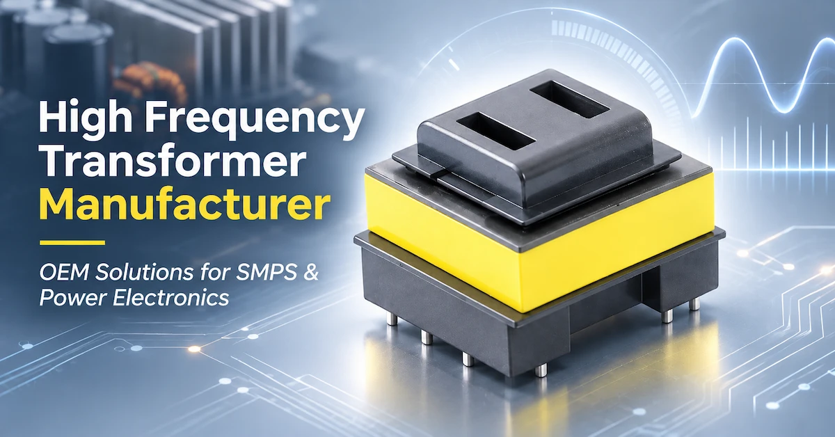
Choosing a high frequency transformer manufacturer is a critical decision for OEM engineers developing switch-mode power supplies (SMPS), isolated DC-DC converters, industrial control systems, and compact electronic equipment.
The challenge is not simply finding a transformer with the correct power rating or physical dimensions. Its magnetic design must match the converter topology, switching frequency, voltage requirements, insulation needs, thermal environment, and production constraints.
Quick Answer: A reliable high frequency transformer manufacturer should help translate electrical and mechanical requirements into a manufacturable transformer specification. OEM buyers should confirm winding design, core material, magnetizing and leakage inductance, insulation construction, thermal limits, and acceptance tests before approving samples or mass production.
COMMONDE, operated by Ningbo Commonde Electronics Co., Ltd., supplies magnetic components including high-frequency transformers, ferrite cores, inductors, and common mode chokes. The company also discusses standard component supply and OEM/ODM customization for electronic equipment manufacturers.
This guide explains how to prepare a complete transformer RFQ, evaluate technical trade-offs, and reduce uncertainty during prototype development and production approval.
Why High Frequency Transformer Selection Matters in SMPS Design
High-frequency transformers are used in switched power-conversion circuits to transfer energy, establish voltage relationships, and provide galvanic isolation where required by the circuit design.
Compared with conventional mains-frequency transformers, high-frequency magnetic designs can achieve more compact constructions under appropriate operating conditions.
However, increasing switching frequency introduces additional engineering challenges.
These include:
-
Magnetic core losses
-
Skin-effect and proximity-effect winding losses
-
Leakage inductance and switching transients
-
Interwinding capacitance and EMI
-
Transformer temperature rise
-
Insulation coordination
-
Manufacturing repeatability
A transformer that performs adequately in a laboratory prototype may require further design refinement before it can be manufactured consistently at scale.
For OEM buyers, the objective is to select a transformer construction that meets the electrical requirements while remaining practical to wind, insulate, test, mount, and reproduce.
Explore the COMMONDE High Frequency Transformer product category for related product information.
Which OEM Buyers Need Custom High Frequency Transformers?
Transformer requirements depend heavily on the final equipment and the role of the magnetic component within the circuit.
| OEM customer type | Typical application | Main technical requirements |
|---|---|---|
| SMPS manufacturer | AC/DC switching power supplies | Efficiency, isolation, thermal management |
| Industrial automation OEM | Control power supplies, auxiliary converters | Operating reliability, dimensions, insulation |
| DC-DC converter manufacturer | Isolated power modules | Turns ratio, inductance, leakage, size |
| LED driver manufacturer | Isolated LED power supplies | Output requirements, thermal behavior, insulation |
| Communication equipment OEM | Network and communication power modules | Compact design, EMI control, supply stability |
| Battery charging equipment manufacturer | Charging and auxiliary power circuits | Voltage conversion, insulation, thermal performance |
| EMS / PCBA manufacturer | Contract assembly of power electronics | Footprint compatibility, approved specifications, repeatable quality |
When Is a High-Frequency Ferrite Transformer Not the Right Choice?
A high-frequency ferrite transformer should not be treated as a universal replacement for a 50/60 Hz transformer.
It must operate within a compatible switching circuit.
Likewise, a transformer designed for one converter topology should not automatically be transferred to another topology simply because its dimensions or turns ratio appear similar.
A custom design is particularly valuable when standard magnetic components cannot meet the required electrical, mechanical, or thermal conditions.
What Specifications Should OEMs Send a High Frequency Transformer Manufacturer?
A successful custom project begins with a complete electrical and mechanical design brief.
Without these inputs, suppliers may propose different constructions that are difficult to compare fairly.
Essential Transformer RFQ Specification Table
| Specification | Information the OEM should provide | Engineering importance |
|---|---|---|
| Converter topology | Flyback, forward, half-bridge, LLC, or other design | Determines the transformer's magnetic operating requirements |
| Input voltage | Minimum, nominal, and maximum input | Defines operating voltage conditions |
| Output requirements | Output voltage, current, number of outputs | Guides turns ratio and winding configuration |
| Output power | Continuous and peak load conditions | Supports electrical and thermal evaluation |
| Switching frequency | Nominal frequency and operating range | Influences ferrite material and winding design |
| Magnetizing inductance | Required target and tolerance, if defined | Important for converter operation |
| Leakage inductance | Required limit or target, with measurement conditions | Influences switching behavior and circuit performance |
| Winding resistance | Applicable maximum DCR values | Helps evaluate copper losses |
| Insulation requirements | Required isolation and dielectric criteria | Supports electrical safety design |
| Mechanical envelope | Maximum dimensions, height, mounting style | Determines PCB and enclosure compatibility |
| Operating environment | Ambient temperature, cooling, duty cycle | Supports thermal design |
| Production requirements | Quantities, documentation and testing expectations | Enables manufacturing and quotation planning |
These are RFQ information fields, not published electrical specifications for a specific COMMONDE transformer.
Exact values must be determined from the customer's circuit and verified against the proposed design.
Why Converter Topology Must Be Defined First
A flyback transformer operates differently from a forward or LLC transformer.
In a flyback converter, the coupled magnetic element stores energy during part of the switching cycle and transfers it to the output during another part. Its magnetizing inductance and core-gap design are therefore fundamental to operation.
In forward converters, the transformer primarily transfers energy during the active switching interval, and the magnetic reset strategy becomes important.
In LLC resonant converters, magnetizing inductance and the relationship between resonant elements must be considered as part of the overall converter design.
Consequently, a transformer manufacturer's design process must begin with the actual circuit topology—not with a generic power rating.
How Ferrite Core Selection Affects Transformer Performance
Ferrite materials are widely used in high-frequency power transformers because suitable grades offer useful magnetic properties at switching frequencies.
However, different ferrite materials have different core-loss, permeability, saturation, and temperature characteristics.
Core Loss and Switching Frequency
Core losses depend on magnetic material, operating frequency, flux-density waveform, and temperature.
A material that performs well in one operating range may produce excessive losses in another.
TDK's technical publications on ferrite materials explain the importance of selecting materials according to operating frequency and magnetic loss characteristics.
For a custom transformer, engineers should evaluate material curves rather than assuming that all ferrite grades behave similarly.
Core Geometry and Winding Space
Common ferrite-core geometries include EE, ER, PQ, EC, and other specialized configurations.
The selected shape influences:
-
Available winding window
-
Magnetic cross-sectional area
-
Mean winding length
-
Overall component dimensions
-
Bobbin and terminal arrangements
-
Cooling and assembly accessibility
For example, PQ constructions are often considered in compact power-conversion projects, but their suitability depends on the complete magnetic and mechanical design.
COMMONDE has an existing technical article comparing these shapes: EE, ER, PQ and EC Ferrite Cores for High Frequency Transformers.
Core geometry alone does not establish power capability or efficiency.
Winding Design: Balancing Leakage Inductance, Copper Loss and EMI
Winding construction is one of the most important factors distinguishing a custom high frequency transformer from a generic component.
1. Leakage Inductance
Leakage inductance results from imperfect magnetic coupling between windings.
In many switching converters, excessive leakage inductance can contribute to voltage spikes, snubber losses, and other undesirable switching behavior.
Texas Instruments discusses winding placement and leakage-inductance control in its application report Flyback Transformer Design for the UCC28600.
Reducing leakage may require changes to winding arrangement or interleaving.
However, tighter coupling can increase interwinding capacitance, potentially influencing common-mode noise.
The objective is not always the lowest possible leakage inductance; it is the value appropriate to the converter and its EMI requirements.
2. Copper Loss
Winding losses depend on conductor resistance and current.
At higher frequencies, skin effect and proximity effect may increase effective AC resistance.
Designers may evaluate conductor dimensions, winding arrangement, multiple strands, or other appropriate winding methods.
The selected method must also be practical to manufacture.
3. Insulation Structure
Primary-to-secondary insulation is especially important in isolated power supplies.
A transformer may require specific wire insulation, tape barriers, winding separation, bobbin arrangements, creepage distances, or clearance distances.
These requirements depend on the applicable end-product safety design and operating conditions.
A high frequency transformer manufacturer should confirm the proposed insulation construction and relevant test requirements before prototype approval.
Comparing COMMONDE Transformer Product Directions
Different transformer-related product structures may be suitable for different OEM requirements.
The following comparison uses product examples listed on COMMONDE's website. It does not represent a verified electrical performance ranking.
| Product example | Product or construction focus | Potential application direction | Specifications to confirm |
|---|---|---|---|
| Ferrite Core High Frequency Transformer | Ferrite-based high-frequency transformer category | Isolated conversion and custom power magnetics | Topology, power, core material, turns ratio, insulation |
| PQ2620 Flyback Transformer | PQ-type flyback transformer construction | Flyback SMPS and auxiliary power conversion | Inductance, leakage, current, thermal conditions, pinout |
| Embedded Ultra-thin Flat Transformer | Compact PCB-mounted transformer-related power assembly | Space-constrained embedded power applications | Whether a complete module is required, input/output ratings, isolation, dimensions |
Important distinction: The embedded ultra-thin product page describes a PCB-level assembly incorporating magnetic and electronic components. It should not automatically be treated as an interchangeable standalone transformer.
Similarly, the PQ2620 product page presents a flyback design direction, but an individual project's exact power capability, winding specification, operating frequency, and test requirements still need confirmation.
Standard Transformer or Custom Transformer?
A standard transformer may be appropriate when its approved electrical, mechanical, and insulation characteristics match the design.
A custom transformer becomes more relevant when the application requires a specific winding arrangement, core geometry, footprint, thermal limit, or insulation structure.
OEM buyers should select the sourcing route based on technical requirements and qualification costs rather than assuming that customization always provides superior performance.
Manufacturing Process: From Engineering Design to Mass Production
A typical custom transformer manufacturing project moves through several technical stages.
The exact manufacturing route depends on the transformer construction.
Step 1: Engineering Requirement Review
The manufacturer reviews the converter schematic, electrical inputs, output requirements, mechanical limitations, and intended operating conditions.
Ambiguous or conflicting requirements should be resolved before the design is finalized.
Step 2: Magnetic and Winding Design
The engineering team evaluates core materials, magnetic geometry, turns ratio, inductance targets, conductor arrangement, insulation construction, and thermal requirements.
The design must consider both electrical performance and manufacturability.
Step 3: Prototype Production
Samples are manufactured using the proposed winding and assembly configuration.
The prototype should have a defined revision and documented construction.
Step 4: Electrical and Mechanical Validation
Samples undergo relevant inspection and testing.
These may include inductance measurements, winding resistance, leakage inductance, turns ratio, polarity, dimensional checks, and dielectric testing where specified.
Step 5: Customer System Verification
The transformer is tested in the actual power converter.
Engineers evaluate operating behavior, losses, temperature rise, switching waveforms, noise, and applicable electrical safety requirements.
Step 6: Production Specification Approval
After validation, the buyer and manufacturer establish the approved drawing, material requirements, acceptance criteria, and change-control arrangements.
Step 7: Batch Manufacturing and Inspection
Production components are manufactured and inspected against the approved specification.
COMMONDE describes winding, forming, testing, and OEM/ODM activities in its company information. The exact processes and equipment available for a specific transformer project should be confirmed with its team.
Quality Control: What Should Be Tested Before OEM Production?
A reliable transformer supplier needs more than a functional prototype.
OEM buyers should establish measurable acceptance criteria for repeat production.
| Test or inspection | Purpose | Important condition |
|---|---|---|
| Winding continuity | Detects open or incorrect connections | Approved pinout and circuit |
| Turns ratio | Checks winding relationships | Defined test method |
| Magnetizing inductance | Verifies the magnetic design | Measurement frequency and conditions |
| Leakage inductance | Evaluates unwanted magnetic leakage | Specified shorted-winding and test configuration |
| DC resistance | Helps control winding losses | Temperature and per-winding limits |
| Polarity / phasing | Verifies winding connection orientation | Approved polarity diagram |
| Dielectric withstand | Evaluates specified insulation requirements | Correct voltage, duration and acceptance conditions |
| Mechanical inspection | Verifies dimensions and mounting | Approved drawings and tolerances |
| Thermal evaluation | Checks operation under load | Representative worst-case environment |
Not every test must be applied identically to every transformer.
The required test plan should match the circuit, insulation design, customer requirements, and approved production specification.
Understanding Certification and Compliance
Quality-management certification is different from product-specific electrical safety approval.
For example, an ISO 9001 certificate relates to quality management, while an applicable insulation-system recognition concerns a defined insulation system and scope.
RoHS or REACH documentation relates to applicable material requirements.
OEM buyers should verify the legal entity, document scope, validity, and relationship to the proposed transformer.
No certification should be assumed to apply to a particular transformer unless the relevant supporting documentation confirms it.
Cost, MOQ and Lead Time: What Determines the OEM Quotation?
The commercial terms for a high-frequency transformer depend on more than the size of the ferrite core.
Important variables include:
-
Magnetic material and core availability
-
Winding complexity and number of outputs
-
Specialized conductors or insulation materials
-
Bobbin and terminal requirements
-
Tooling or custom fixtures
-
Prototype revisions and verification tests
-
Production quantities and inspection requirements
For example, a multi-output isolated transformer with complex winding and insulation requirements may need more development and validation than a simpler construction.
However, manufacturing cost cannot be established from design complexity alone.
The manufacturer must review the actual requirements and order conditions.
How OEM Buyers Can Reduce Procurement Risk
A practical procurement strategy is to separate three cost categories:
Design and development cost: Engineering review, prototypes, revisions, and any applicable tooling.
Component production cost: Materials, winding, assembly, inspection, packaging, and volume conditions.
Qualification and supply-chain cost: Electrical validation, documentation, potential redesign, shipment planning, and production continuity.
When comparing quotations, buyers should use consistent requirements and quantities.
Do not assume that published sample lead times, general pricing, or catalog descriptions apply to every custom project.
How to Prepare an Effective High Frequency Transformer RFQ
A strong RFQ reduces unnecessary technical exchanges and helps manufacturers evaluate feasibility.
Before requesting a quotation, OEM buyers should prepare:
-
Converter topology: Flyback, forward, LLC, or other defined circuit.
-
Electrical input: Minimum, nominal, and maximum input voltage.
-
Output requirements: Voltage, current, number of windings, and load profile.
-
Switching conditions: Frequency range, operating mode, and relevant waveforms.
-
Magnetic requirements: Magnetizing inductance, leakage inductance, or other established targets.
-
Mechanical requirements: Maximum height, footprint, pinout, and mounting method.
-
Insulation and environment: Applicable electrical isolation, temperature, and operating conditions.
-
Production details: Prototype quantity, annual demand, inspection requirements, and target schedule.
Where possible, include the converter schematic, relevant drawings, and an existing transformer specification.
For a custom project, the manufacturer may need further engineering discussions before confirming the final design.
Looking for a high frequency transformer manufacturer for your next OEM project?
Explore COMMONDE's High Frequency Transformer range and submit your application requirements.
Provide your switching topology, electrical specifications, insulation requirements, and mechanical constraints to begin a technical review.
Frequently Asked Questions
1. What Does a High Frequency Transformer Manufacturer Produce?
A high frequency transformer manufacturer supplies magnetic components designed for compatible high-frequency power-conversion circuits. Products may include ferrite-core transformers, custom flyback transformers, and other application-specific magnetic assemblies.
2. Can COMMONDE Manufacture Customized High Frequency Transformers?
COMMONDE describes OEM/ODM magnetic-component support. Whether a particular transformer topology, core, winding structure, insulation requirement, or volume can be supported must be confirmed through technical review and quotation.
3. What Is the Difference Between a Flyback Transformer and a Conventional Power Transformer?
A flyback transformer functions as a coupled energy-storage element within its switching cycle, while other transformer configurations primarily transfer energy during defined switching intervals. Their magnetic requirements are therefore different.
4. How Do I Choose the Right Ferrite Core for a High Frequency Transformer?
Evaluate the converter topology, switching frequency, flux-density conditions, core losses, winding space, temperature, and mechanical constraints. Do not select a core based only on shape or nominal size.
5. Why Is Leakage Inductance Important?
Leakage inductance can influence voltage spikes, switching losses, regulation, and EMI. Its acceptable value depends on the circuit topology and the complete converter design.
6. What Causes a High Frequency Transformer to Overheat?
Potential causes include excessive core losses, winding resistance, AC copper losses, high operating current, inadequate cooling, or operation outside the intended design conditions.
7. Can the Same Transformer Be Used in Flyback and LLC Converters?
Not automatically. These converter topologies have different magnetic operating requirements. A transformer must be designed or validated for the actual circuit.
8. Which Tests Should OEM Buyers Require Before Mass Production?
Depending on the application, tests may include turns ratio, magnetizing inductance, leakage inductance, DCR, polarity, insulation verification, dimensional inspection, and system-level thermal evaluation.
9. What Determines Custom Transformer MOQ and Lead Time?
Material availability, core and bobbin requirements, winding complexity, tooling, sample approval, production quantity, and testing requirements may affect MOQ and lead time. These conditions should be confirmed through an individual quotation.
10. What Information Should I Send to Request a Custom Transformer Quote?
Provide the converter topology, input and output specifications, switching frequency, required inductance characteristics, insulation conditions, mechanical drawings, operating environment, prototype quantity, and expected production volume.
Conclusion
Choosing a high frequency transformer manufacturer requires a structured approach connecting power-converter design, magnetic engineering, manufacturing capability, and quality verification.
For SMPS OEMs, the most important decisions involve selecting appropriate core materials, controlling winding losses and leakage inductance, confirming insulation requirements, and validating the transformer under actual operating conditions.
A complete design brief enables more meaningful technical discussions, reduces unnecessary specification changes, and supports consistent sample and production approval.
COMMONDE offers high-frequency transformer-related products and discusses OEM/ODM magnetic-component solutions for industrial and electronic equipment applications.
Explore the COMMONDE High Frequency Transformer product category, review its product catalog, or contact COMMONDE for an OEM transformer inquiry.
Share your circuit requirements, electrical specifications, mechanical constraints, and expected purchasing quantities to discuss suitable transformer constructions, customization feasibility, and the next steps toward sample development.