Why Ferrite Core Geometry Matters
Ferrite material affects magnetic loss and permeability, while core geometry determines how the transformer can be wound, cooled, mounted, and manufactured.
The core shape affects:
- Winding-window area
- Magnetic cross-section
- Mean turn length
- Copper loss
- Leakage inductance
- Transformer height
- Thermal path
- Bobbin availability
- Production method
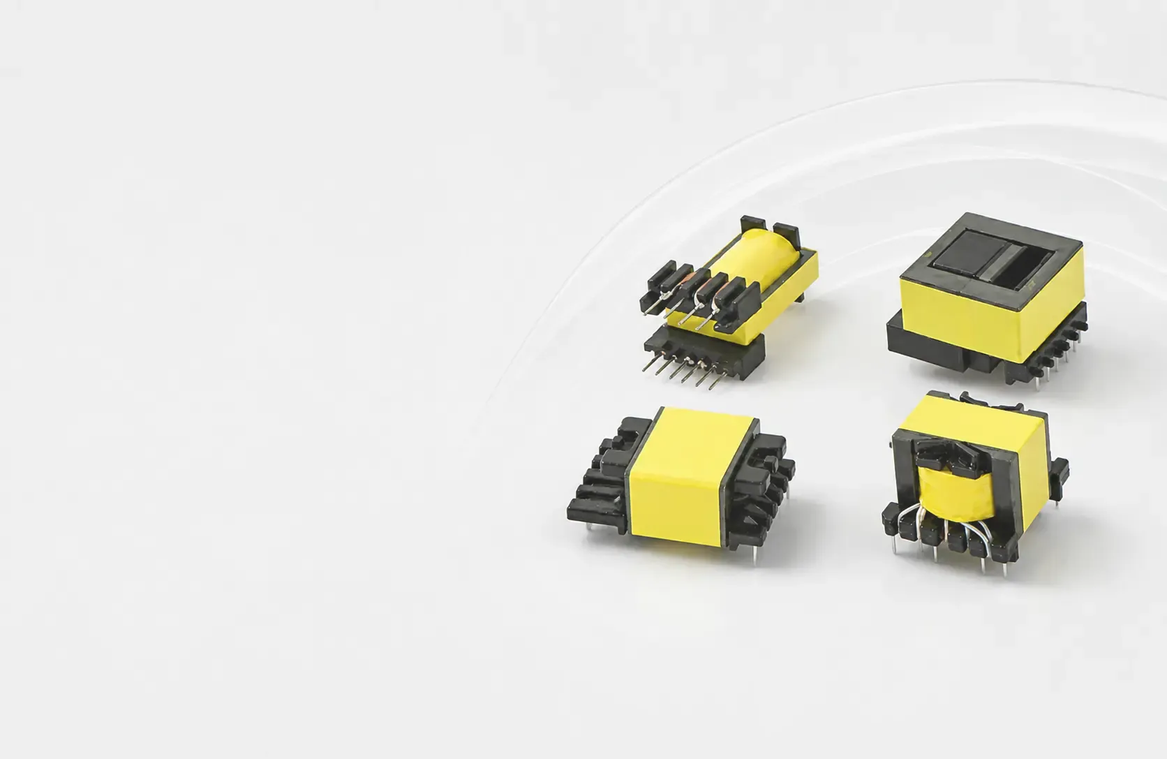
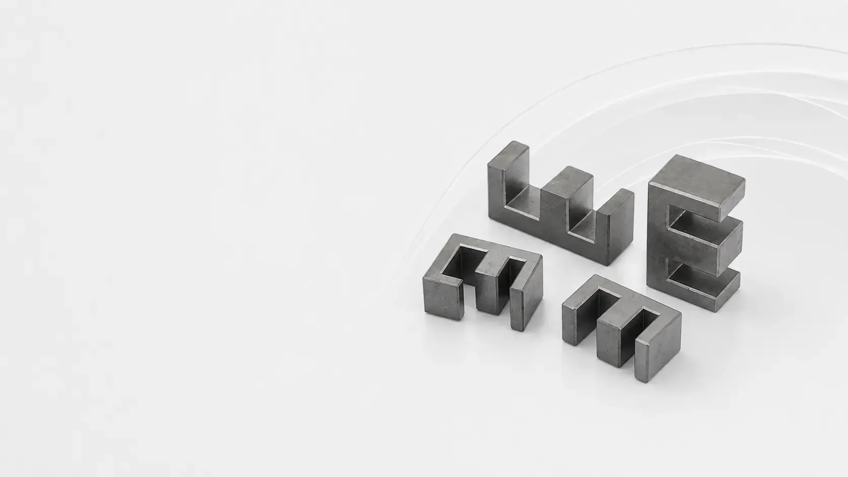
EE Ferrite Cores
EE ferrite cores are among the most widely used core shapes for high-frequency transformers and inductors.
Their key advantages include:
- Broad size availability
- Simple bobbin construction
- Convenient winding access
- Established production processes
- Cost-effective volume manufacturing
EE cores are commonly used in flyback transformers, forward converters, auxiliary power supplies, communication equipment, and consumer electronics.
ER Ferrite Cores
ER ferrite cores use a rounded center leg that can reduce mean turn length and improve winding utilization.
They are often considered when designers need:
- Reduced transformer profile
- Shorter copper length
- Compact construction
- Improved winding efficiency
The actual benefits depend on the selected core size, bobbin, winding method, frequency, and thermal conditions.
PQ Ferrite Cores
PQ ferrite cores provide a favorable balance between magnetic cross-section and winding area in a compact volume.
Their rounded center post may help reduce the average length per turn, which can reduce copper loss.
PQ cores are frequently evaluated for:
- High-density power supplies
- Industrial converters
- Communication power systems
- Charging equipment
- Higher-power transformer designs
EC Ferrite Cores
EC ferrite cores combine an E-type structure with a rounded center leg.
They provide a balanced relationship between:
- Winding area
- Magnetic cross-section
- Copper length
- Mechanical dimensions
- Power capability
EC cores are used in power-conversion designs where compact size and efficient winding utilization are required.
Core Shape Comparison
| Core Family | Primary Strength | Main Consideration |
|---|---|---|
| EE | Availability and simple construction | May require more volume |
| ER | Reduced profile and winding utilization | Confirm bobbin options |
| PQ | Compact power design | Winding access may be limited |
| EC | Balanced magnetic and winding geometry | Availability varies by size |
How to Select a Transformer Core
Define the Electrical Requirements
Confirm:
- Converter topology
- Input and output voltage
- Power
- Switching frequency
- Duty cycle
- Flux-density limit
- Efficiency target
- Isolation requirements
Check the Winding Window
The winding window must accommodate:
- Primary winding
- Secondary winding
- Auxiliary winding
- Insulation layers
- Safety margins
- Creepage and clearance requirements
A core can have sufficient magnetic area but still be unsuitable if the winding window is too small.
Review Thermal Performance
Calculate both core loss and copper loss. Consider airflow, PCB conduction, winding hot spots, enclosure temperature, and the required insulation temperature class.
Confirm Manufacturability
Discuss bobbin supply, winding method, terminals, insulation tape, core gap, adhesive or clamp, automated testing, tolerances, and production volume.
Frequently Asked Questions
Which core provides the highest power density?
Power density depends on core size, material, frequency, flux swing, winding, topology, and cooling. PQ and similar compact shapes are often evaluated, but calculations are required.
Can an EE transformer be changed directly to a PQ core?
No. The winding, turns, flux density, leakage inductance, thermal behavior, bobbin, and PCB layout must be redesigned or validated.
Why is the bobbin important?
The bobbin determines usable winding space, insulation arrangement, pin configuration, creepage distance, and compatibility with the production process.