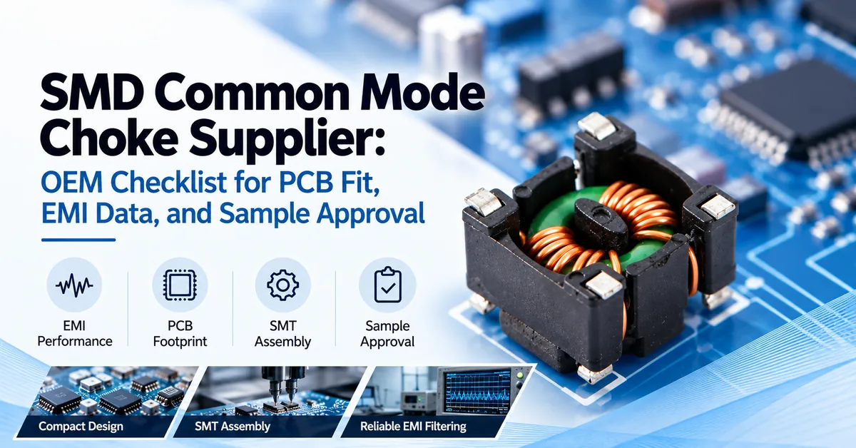
Selecting an SMD common mode choke manufacturer involves more than finding a component with suitable electrical specifications. For OEM electronics manufacturers, production consistency, winding quality, solderability, dimensional control, and repeatable electrical testing can determine whether a filter component performs reliably across thousands of assembled circuit boards.
The essential manufacturing requirement is consistency: an approved surface-mount common mode choke must retain its specified electrical and mechanical characteristics from engineering samples through subsequent production lots.
COMMONDE, a magnetic components manufacturer in Ningbo, China, supplies common mode chokes, inductors, high-frequency transformers, and ferrite cores. The company also discusses OEM/ODM customization for magnetic components.
This guide explains the production controls OEM buyers should evaluate, the evidence required before manufacturing approval, and how to prepare a more effective custom magnetic component inquiry.
Why Manufacturing Consistency Matters for SMD Common Mode Chokes
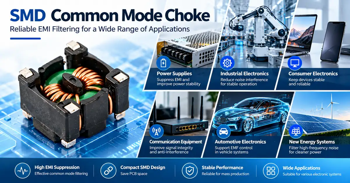
An SMD common mode choke is a magnetically coupled filtering component designed to suppress unwanted common-mode interference on paired conductors.
Its windings are arranged so that normal differential currents produce largely opposing magnetic flux, while common-mode currents generate reinforcing flux and encounter increased impedance.
The principle is straightforward, but achieving repeatable electrical characteristics requires attention to magnetic materials, winding geometry, terminal connections, and inspection methods.
Small variations may affect:
-
Common-mode inductance and impedance response
-
DC resistance and temperature rise
-
Leakage inductance and differential-mode behavior
-
Mechanical dimensions and terminal alignment
-
Soldering performance during SMT assembly
-
Production repeatability between manufacturing lots
For this reason, a manufacturer should be evaluated on its ability to reproduce an approved design—not only on the performance of one sample.
Explore the COMMONDE Common Mode Chokes product category for the broader product family.
Which OEM Buyers Benefit From SMD Manufacturing Support?
Surface-mount magnetic components are relevant to electronics manufacturers seeking compact PCB assemblies and automated production processes.
| Buyer type | Manufacturing requirement | Main evaluation priority |
|---|---|---|
| Power supply OEM | Compact filter components for power conversion boards | Impedance, rated current, DCR, thermal performance |
| Industrial control manufacturer | Consistent parts for automated PCB assembly | Dimensional stability, solderability, EMI validation |
| Communication equipment OEM | Filtering within space-constrained electronics | Frequency response, signal integrity, package dimensions |
| EMS / PCBA manufacturer | Reliable material feeding and repeatable soldering | Tape-and-reel compatibility, terminal geometry, inspection |
| Electronics sourcing company | Stable components for ongoing production programs | Traceability, change control, quality documentation |
When is an SMD choke not the appropriate choice?
A compact SMD construction should not be assumed suitable for high-voltage mains filtering, high-current power conversion, or high-speed signal lines without application-specific validation.
Electrical clearance, insulation, differential-mode behavior, thermal limits, and relevant product qualifications may require another construction.
How Are SMD Common Mode Chokes Manufactured?
A typical manufacturing route involves several controlled operations. The exact sequence depends on whether the design uses a wound toroidal core, a molded construction, another magnetic structure, or a specialized termination system.
The following is a representative engineering workflow, not a claim that every listed process or machine is used for every COMMONDE SMD product.
1. Magnetic Core Material Selection
The manufacturing process begins with selecting a magnetic material and geometry suitable for the intended filtering characteristics.
Depending on the design, material selection may consider permeability, core loss, frequency-dependent behavior, temperature characteristics, and mechanical stability.
Manufacturing checks may include material identification, core dimensions, visible damage, and specified magnetic characteristics.
A magnetic material cannot be considered interchangeable solely because the replacement core has the same external dimensions.
2. Winding Design and Production
Winding geometry influences inductance, coupling, parasitic capacitance, resistance, and high-frequency behavior.
Critical variables may include the number of turns, conductor dimensions, insulation system, winding tension, and physical arrangement.
Manufacturing teams should control the parameters identified as critical to the approved design.
For OEM procurement, the important question is not simply whether winding is automated, but whether the manufacturer can document and control the characteristics affecting the finished component.
3. Terminal Formation and Electrical Connections
In an SMD assembly, terminal construction is particularly important because the component must connect consistently to PCB pads.
Poor terminal geometry or electrical connections may contribute to unstable resistance, weak solder joints, mounting defects, or inconsistent assembly results.
Relevant checks can include terminal dimensions, coplanarity where applicable, connection integrity, solderability, and mechanical damage.
4. Component Assembly and Dimensional Control
The magnetic structure, winding, support materials, and terminals are assembled according to the approved design.
Dimensional consistency affects the ability of automated placement equipment to position components accurately.
For low-profile electronics, height tolerances may be as important as the component footprint.
5. Electrical Testing and Final Inspection
Finished components should be evaluated against defined acceptance criteria.
Depending on the application and design, testing may cover winding continuity, DCR, inductance, impedance, insulation characteristics, and physical dimensions.
The test method must be specified. An inductance value or impedance result without its frequency, connection method, and relevant conditions may not support meaningful comparison.
Critical Manufacturing Specifications OEM Buyers Should Confirm
A capable SMD common mode choke manufacturer should be able to identify which specifications apply to the proposed part and how those values are verified.
| Specification | Engineering importance | Manufacturing or validation evidence |
|---|---|---|
| Common-mode impedance | Determines filtering behavior across the relevant noise frequencies | Frequency-response data and measurement conditions |
| Common-mode inductance | Describes magnetic behavior under specified test conditions | Measurement frequency, tolerance, test setup |
| Rated current | Helps establish continuous operating capability | Rating definition, ambient conditions, derating data |
| DC resistance (DCR) | Influences voltage drop and copper heating | Per-winding resistance limits and test procedure |
| Leakage inductance | May affect differential-mode filtering and system behavior | Specified measurement method, if required |
| Magnetic core material | Influences magnetic and thermal performance | Material identification and relevant characteristics |
| Package dimensions | Determines PCB and enclosure compatibility | Controlled mechanical drawing and tolerances |
| Terminal geometry | Affects positioning and solder-joint formation | Land pattern, terminal dimensions, solderability criteria |
| Reflow compatibility | Determines suitability for the planned SMT process | Approved soldering profile and process limitations |
| Environmental requirements | Supports intended operating conditions | Applicable temperature limits and qualification evidence |
Important: This is an engineering specification checklist, not a published datasheet for a specific COMMONDE model. Actual ratings and available documents should be confirmed for the proposed product.
Why DCR and Current Ratings Matter During Production
DC resistance affects conduction losses and temperature rise.
For a winding carrying current, resistive loss can be approximated as:
P = I² × R
where I is the current and R is the relevant winding resistance.
Manufacturing variation in conductor dimensions, winding length, and electrical connections can affect resistance.
However, temperature rise also depends on the PCB, airflow, enclosure, and neighboring heat sources. A part's stated rated current should always be interpreted using its defined test conditions.
Why Frequency-Response Testing Matters
A choke does not provide identical impedance across all frequencies.
Its response depends on magnetic properties, winding construction, and parasitic effects.
Manufacturers and buyers should therefore evaluate the appropriate impedance-frequency response rather than relying exclusively on a single nominal inductance value.
TDK Electronics' published SMD choke datasheets illustrate how frequency-response curves and current derating information can be used in component evaluation. Those example data belong to TDK products and should not be treated as COMMONDE product ratings.
SMT Assembly Compatibility: From Component Production to PCB Manufacturing
A component that passes electrical testing may still create problems on an automated PCB assembly line.
Manufacturers should therefore consider downstream assembly requirements before finalizing the component construction.
PCB Footprint and Placement
The engineering team should confirm:
-
Component length, width, and maximum height
-
Terminal configuration and pin orientation
-
Recommended PCB land pattern
-
Placement orientation and available machine clearance
-
Adjacent component spacing and thermal conditions
A supplier drawing and an EMS-approved footprint should refer to the same component revision.
Reflow Soldering and Solderability
Surface-mount components must tolerate their specified assembly process.
The buyer should request the applicable reflow guidance, termination information, and solderability requirements.
Do not assume every SMD magnetic component supports the same peak temperature, thermal exposure, or reflow-cycle count.
IPC J-STD-001 and IPC-A-610 provide widely used industry guidance for soldered electronic assemblies and their acceptability. Their relevance should be evaluated against the actual product and assembly requirements; citing them does not establish certification of a magnetic component manufacturer.
Component Packaging for Automated Assembly
For EMS operations, packaging should be evaluated alongside the component itself.
Relevant purchasing information includes packaging format, orientation, reel quantities, component protection, labeling, and traceability.
Any tape-and-reel or pick-and-place compatibility claim should be confirmed for the actual ordering code.
Comparing SMD and Other Common Mode Choke Manufacturing Approaches
Different structures create different manufacturing and installation considerations.
| Product construction | Typical assembly approach | Manufacturing consideration | Suitable procurement situation |
|---|---|---|---|
| SMD common mode choke | Surface-mount PCB assembly | Terminal geometry, compact winding, solderability, dimensional control | Space-constrained boards and automated SMT production |
| Square through-hole choke | Through-hole installation | Winding consistency, pin positioning, mechanical fit | Equipment using through-hole PCB assembly |
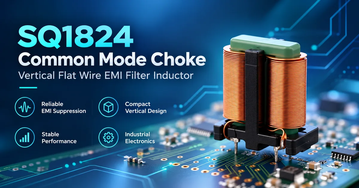
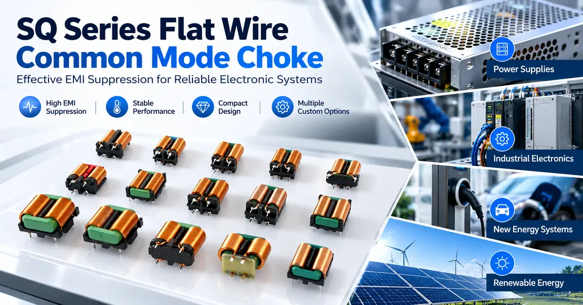
| Flat-wire common mode choke | Often through-hole or other application-specific mounting | Conductor forming, insulation, termination quality | Applications where conductor geometry and current handling are important |
| Multi-chamber bobbin choke | Commonly through-hole assembly | Winding separation, bobbin dimensions, insulation control | Designs requiring a specific separated-winding structure |
These are construction categories rather than manufacturer model ratings. A fair comparison must use actual electrical, thermal, mechanical, and application requirements.
COMMONDE provides relevant product examples:
For a separate discussion of construction trade-offs, read SMD vs Toroidal vs Flat Wire Common Mode Chokes.
Quality Control for Repeatable OEM Production
Production quality should be assessed through documented inspection and manufacturing controls.
Incoming Quality Control
Incoming inspection may verify the identity and condition of magnetic cores, winding conductors, terminals, and other specified materials.
Material consistency is important because substitutions may change electrical or assembly behavior.
In-Process Quality Control
Process checks can cover winding configuration, terminal formation, electrical continuity, dimensional characteristics, and other critical features.
The appropriate sampling method depends on the component, risk, and agreed production requirements.
Final Quality Control
Final inspection should verify agreed electrical and mechanical characteristics.
The buyer and manufacturer should establish acceptance limits, measurement conditions, and handling of nonconforming material.
Lot Traceability and Engineering Change Control
For repeat orders, buyers should ask how lots are identified and how significant changes to materials, construction, manufacturing processes, or test methods are communicated.
Traceability is particularly important when a later PCB failure investigation requires identification of the affected component batches.
COMMONDE describes manufacturing and quality-related activities on its About Us page. Buyers should request the part-specific quality evidence and process details required for their own approval procedures.
OEM/ODM Customization: What Can Be Discussed With the Manufacturer?
Customization may be useful when a standard component does not meet the desired mechanical or electrical conditions.
Depending on manufacturing feasibility, discussions may concern:
-
Target common-mode impedance and frequency range
-
Winding configuration and electrical characteristics
-
Magnetic material selection
-
Package size and maximum height
-
Terminal layout and PCB footprint
-
Operating current and resistance limits
-
Assembly compatibility
-
Testing and documentation requirements
Not every characteristic can be adjusted independently.
Increasing winding turns, changing magnetic materials, or reducing package dimensions can introduce trade-offs involving resistance, parasitic capacitance, thermal behavior, cost, and manufacturability.
A practical OEM project starts with an approved requirement document, followed by feasibility evaluation, sample development, validation, and production release.
Contact COMMONDE to discuss whether a particular SMD construction can be supplied or customized for your project.
Manufacturing Cost, Lead Time, and Production Risks
An OEM should evaluate the total cost of qualification and ongoing production—not only the quoted unit price.
Cost and schedule may depend on material availability, construction complexity, tooling, required testing, order quantities, and documentation requirements.
| Purchasing consideration | Potential risk | Recommended OEM action |
|---|---|---|
| Custom magnetic design | Additional engineering and validation work | Confirm feasibility and acceptance criteria before ordering |
| Specialized materials | Longer or less predictable material sourcing | Confirm material availability and approved alternatives |
| Tight dimensional tolerances | Production and inspection complexity | Specify critical dimensions and realistic tolerances |
| Nonstandard packaging | EMS handling or feeding problems | Confirm packaging requirements before production release |
| Incomplete electrical data | Additional testing and redesign | Request part-specific evidence early |
| Uncontrolled design changes | Differences between approved and delivered parts | Establish documented change-notification requirements |
MOQ, sample lead time, tooling charges, and mass-production schedules should be confirmed through a project-specific quotation.
Published company-level lead-time statements should not be assumed to apply to all customized SMD products.
What Should OEM Buyers Include in a Manufacturing RFQ?
A detailed RFQ helps the engineering and manufacturing teams assess a project efficiently.
Provide the following information:
1. Product application: Device type, circuit position, and whether the component is intended for a power line or signal interface.
2. Electrical requirements: Voltage, continuous and transient current, impedance-frequency targets, DCR limits, and other relevant characteristics.
3. PCB and mechanical requirements: Footprint, terminal arrangement, maximum height, mechanical drawing, and available mounting space.
4. Assembly requirements: SMT process, applicable reflow conditions, packaging preferences, and inspection requirements.
5. Environmental requirements: Ambient temperature, enclosure conditions, duty cycle, and relevant product qualification requirements.
6. Commercial requirements: Prototype quantity, estimated annual demand, intended production schedule, and expected documentation.
A complete requirement package gives an SMD common mode choke manufacturer a stronger basis for discussing feasibility, samples, manufacturing controls, and quotation.
For additional product information, explore the COMMONDE product catalog or submit your project requirements.
Frequently Asked Questions
1. What Does an SMD Common Mode Choke Manufacturer Produce?
An SMD common mode choke manufacturer produces magnetic filtering components intended for compatible surface-mount PCB assembly. The specific construction, materials, electrical characteristics, and production capabilities depend on the part series.
2. How Does the Manufacturing Process Affect EMI Performance?
Core material, winding geometry, conductor placement, and parasitic effects influence the electrical response. Controlling critical production characteristics helps maintain consistency between samples and subsequent manufacturing lots.
3. Can COMMONDE Manufacture Customized SMD Common Mode Chokes?
COMMONDE discusses OEM/ODM magnetic-component solutions. Whether a particular SMD structure, package, electrical target, or volume is feasible must be confirmed through technical evaluation and quotation.
4. What Is the Difference Between SMD and Through-Hole Manufacturing?
SMD components are designed for surface-mount assembly, while through-hole components use leads installed through PCB holes. These approaches have different terminal, assembly, inspection, and mechanical requirements.
5. How Are SMD Common Mode Chokes Tested During Production?
Applicable tests may include electrical continuity, resistance, inductance, impedance, dimensional inspection, and solderability checks. Actual production testing depends on the approved specification and agreed inspection plan.
6. Why Is Winding Consistency Important?
Winding geometry affects electrical characteristics such as inductance, coupling, resistance, and parasitic behavior. Process control helps reduce unwanted variation in the finished component.
7. Can an SMD Choke Be Used in Automotive Electronics?
A component must be evaluated against the electrical, environmental, reliability, documentation, and qualification requirements of the specific automotive application. SMD construction alone does not establish automotive qualification.
8. What Documents Should OEM Buyers Request Before Mass Production?
Useful documents include the approved specification, mechanical drawing, relevant electrical test information, material or compliance declarations, packaging details, acceptance criteria, and change-control arrangements.
9. What Factors Affect Custom SMD Choke MOQ and Lead Time?
Material sourcing, tooling, construction complexity, test requirements, order volume, and production scheduling may affect MOQ and lead time. These conditions require confirmation for the specific project.
10. How Can OEM Buyers Reduce SMD Common Mode Choke Production Risks?
Use clear technical requirements, approve representative samples, validate the component in the actual PCB assembly, define acceptance criteria, and establish traceability and engineering change controls before mass production.
Conclusion
Choosing the right SMD common mode choke manufacturer means evaluating both electrical engineering capability and manufacturing repeatability.
Magnetic material control, winding consistency, terminal quality, SMT compatibility, electrical testing, and production documentation all contribute to successful OEM integration.
For electronics manufacturers planning a new design or reviewing an existing component supply chain, a clear RFQ and part-specific validation process can reduce uncertainty before production.
COMMONDE supplies magnetic components and discusses OEM/ODM solutions for customer applications. Explore the SMD Common Mode Choke or contact COMMONDE for a custom manufacturing inquiry.
Share your electrical requirements, PCB drawing, operating conditions, and expected order quantities to discuss available product options, manufacturing feasibility, and the next steps toward sample evaluation.