SMD Common Mode Choke for Compact PCB Noise Suppression
An SMD Common Mode Choke is used when a circuit needs cleaner power or quieter signal lines without giving up board space. In compact electronics, unwanted common-mode noise can cause EMI issues, unstable operation, or failed compliance testing. This kind of surface-mount choke helps block high-frequency noise while keeping the current path compact and suitable for automated PCB assembly.
Product Overview
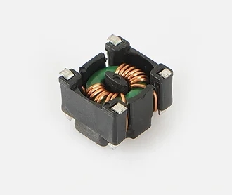
The part shown is a small square, surface-mount magnetic component with a black molded body, visible copper windings, and a low-profile block form. The structure suggests a shielded inductor or common-mode choke style component designed for use on dense circuit boards. Because only the image is available, exact electrical parameters cannot be confirmed, but the visible construction clearly points to a passive component used for filtering, smoothing, or noise suppression in power and signal circuits.
For buyers, the main value is straightforward: reduce electromagnetic interference in a small footprint. That matters in switching power supplies, embedded boards, industrial controllers, and consumer electronics where PCB area is limited and stable operation depends on clean electrical behavior.
Visible Construction and Design Features
Compact square package
The component has a square or rectangular footprint, which is common in SMD passive parts intended for automated placement. This shape supports efficient board layout and simplifies integration into standard assembly lines.
Shielded-looking magnetic body
The dark molded exterior suggests a protected magnetic assembly. A shielded structure is often preferred when designers want to limit magnetic leakage, reduce interference with nearby components, and improve layout flexibility on crowded boards.
Exposed copper winding structure
The visible winding around the central core indicates a coil-based magnetic element. In a common-mode choke, winding geometry is important because it affects impedance, filtering behavior, and thermal performance. The image shows a carefully assembled magnetic package, though the exact winding configuration cannot be verified from the exterior alone.
Four-terminal/termination layout
Four corner termination points are visible, which is consistent with a surface-mount design intended for reliable solder attachment. This type of terminal arrangement is helpful for mass production and can support stable mechanical retention during reflow soldering.
Key Specifications and Capabilities to Confirm
Because the product image does not show a part number or datasheet, buyers should confirm the following before selecting it for a design:
- Inductance or common-mode impedance
- Rated current and saturation behavior
- DC resistance
- Working frequency range
- Package dimensions and height
- Temperature rating
- Insulation and dielectric requirements, if used in sensitive circuits
These parameters determine whether the component is suitable for a specific power supply, data line, or noise-filtering stage. A visually similar magnetic part can perform very differently once it is placed in a real circuit, so matching the electrical specification to the application is essential.
Materials and Finish Options
From the image, the component appears to combine a ferrite-style or molded magnetic body with copper windings and metallic terminations. The body finish is matte black, which is common for molded magnetic parts and helps reduce visual contrast on the PCB. The green internal support material may be part of the insulating base or core structure, but the exact composition is not identifiable from the image alone.
In actual production, options may vary by product family and can include different magnetic core materials, lead finish choices, and encapsulation styles. Buyers typically select these based on electrical loss, thermal performance, solderability, and long-term reliability requirements.
Manufacturing Process
Based on the visible structure, this type of component is likely produced through a passive component assembly process that includes coil winding, core placement, terminal formation, and encapsulation or molding. In practical terms, the process may involve automated winding equipment, magnetic core assembly, and final packaging designed to support surface mounting.
For a common mode choke or shielded power inductor, manufacturing accuracy matters. Coil alignment, termination consistency, and body integrity all influence how the part behaves under current load and high-frequency noise conditions. Even when the part is small, the process must support repeatable electrical performance from batch to batch.
Typical Application Scenarios
This component style is commonly used in circuits that need filtering or suppression of electrical noise. Typical use cases include:
- DC-DC converter input and output filtering
- EMI and RFI suppression on power lines
- Signal conditioning for sensitive electronic modules
- Current smoothing in compact embedded systems
- Consumer electronics with dense PCB layouts
- Industrial control boards and automation devices
In these environments, the choke or inductor helps keep conducted noise under control and can improve the stability of the overall system. Designers often place this kind of part near switching regulators, connectors, or noisy interface sections where filtering is most effective.
Quality Control Considerations
For passive magnetic components, quality control should focus on measurable electrical and mechanical criteria. Buyers should ask for inspection and testing methods that match the intended application. Common checks may include visual inspection of winding integrity, terminal alignment, solderability, dimensions, resistance, inductance, and functional verification against the target circuit requirement.
Since exact ratings are not provided here, it is important not to assume suitability based on appearance alone. A compact SMD Common Mode Choke may look robust, but the final choice should still be driven by datasheet values and validation in the target PCB environment.
Customization Guidance for OEM and ODM Buyers
If this component is being sourced for a custom electronic product, the most useful customization points are usually electrical rating, size, termination style, and packaging format. Buyers may need a version optimized for a specific current level, a tighter height limit, or a more demanding EMI environment. In some cases, the preferred option is not a redesign of the magnetic structure, but a careful selection from an existing family that already matches the board constraints.
When requesting customization, provide the circuit function, operating current, noise frequency range, board space, and environmental conditions. These details help the supplier recommend a component that can fit the layout and perform reliably in production.
How to Choose the Right Part
Selection should start with the circuit goal. If the priority is common-mode noise suppression, the impedance behavior and line configuration matter most. If the part is acting as a power inductor, current handling, inductance value, and DCR become more important. The package size, solder pad design, and thermal behavior should also be checked against the PCB layout.
Other practical decision factors include availability, consistency between batches, and compatibility with automated pick-and-place assembly. For high-volume manufacturing, stable supply and predictable solder performance can be just as important as the electrical specification.
Why This Component Fits Modern Electronics
Modern devices are smaller, faster, and more sensitive to electrical noise than older designs. That creates pressure on the PCB designer to solve EMI and power-quality issues without adding bulky discrete parts. A compact SMD Common Mode Choke addresses that problem by combining surface-mount convenience with magnetic filtering capability in a footprint that suits dense layouts.
The visible construction in this part reflects the same priorities seen across current passive component design: small size, automated assembly compatibility, and reliable noise control in a limited board area.
Request Technical Support or a Quote
If you are evaluating this component for a new design, the best next step is to confirm the electrical parameters against your circuit requirements. Share your target inductance, current, frequency range, and board constraints so the correct version can be matched to your application. For sourcing support, packaging questions, or OEM selection help, contact the supplier with your specification sheet and sample requirements.