Multi chamber bobbins Common Mode Choke Overview
The Multi chamber bobbins Common Mode Choke is a passive EMI suppression component used to reduce unwanted noise on power and signal lines. For buyers working on power supplies, chargers, inverters, industrial boards, or other electronic assemblies, the main problem is often not basic circuit function but conducted noise that can interfere with nearby circuits or make compliance testing difficult. A common mode choke helps address that issue by blocking common-mode interference while allowing the intended current path to operate normally.
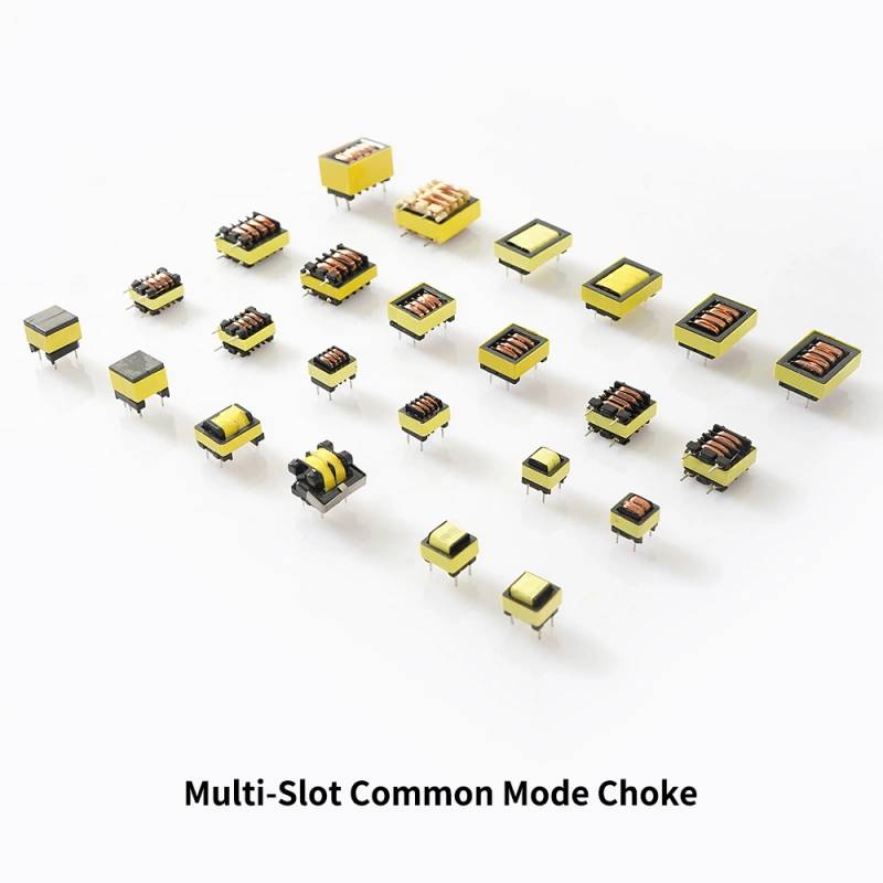
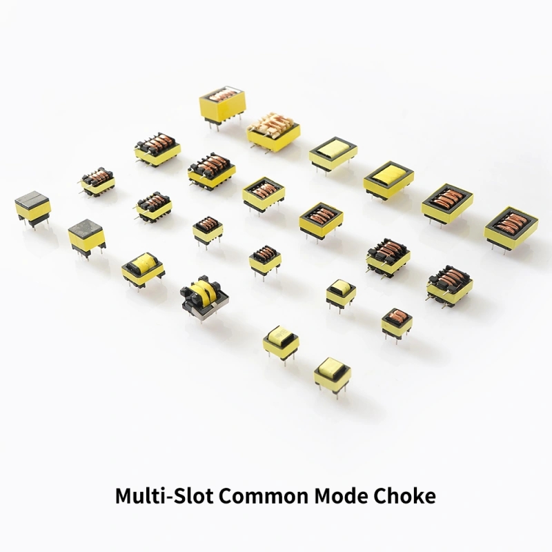
From the visible product structure, this component family uses a rectangular, low-profile magnetic assembly with through-hole terminals, a wound coil section, and an insulated ferrite or tape-wrapped core housing. The multi-slot bobbin format suggests a construction intended to organize windings, support spacing, and make the magnetic component easier to assemble in production. It is a practical choice when a designer needs a compact EMI filter element that can be integrated into a board-mounted layout.
Product Structure and What It Solves
A common mode choke is typically placed in series with lines that carry useful current but are also vulnerable to high-frequency noise. Instead of changing the main power path, it targets the common-mode component that appears on both conductors. This is why the part is widely used in circuits where conducted emissions, line noise, or cross-coupling need to be reduced.
The visible bobbin and core arrangement in this product family points to a wound magnetic component built for filtering rather than energy storage. The multiple chambers or slots help separate windings and support repeatable coil placement. That structure can be useful when the design needs clearer winding organization and a stable base for through-hole assembly. Because exact electrical values are not shown, the product should be evaluated as a component family rather than a single fixed specification.
Visible Specifications and Construction Features
Package and Mounting Style
The units shown use through-hole pin terminals extending from the underside. This mounting style is common in power electronics because it provides mechanical stability and is easy to solder onto conventional printed circuit boards. The block-shaped body appears low profile, which can help when board height is limited.
Core and Bobbin Layout
Most parts show a yellow insulated ferrite or tape-wrapped core housing. Some units also show a black plastic or molded bobbin/frame structure. The top face reveals copper winding coils on many samples, indicating wound magnetic construction rather than a fully encapsulated hidden package. The multi-slot bobbin arrangement may support multiple isolated windings or improved winding organization, although exact spacing, pin pitch, and winding count are not visible.
Size Variants
Multiple package sizes are present in the product set. That is useful for engineers because EMI filter components often need to fit different PCB footprints, power levels, and thermal envelopes. A compact board may require a smaller body, while higher-noise or higher-current designs may need a larger magnetic structure.
Materials and Finish Options
Based on visible features, the product family includes ferrite-type magnetic material or a tape-wrapped magnetic core housing, copper windings, and a molded bobbin or frame in some variants. These are standard material categories for wound magnetic components used in EMI suppression.
The finish appears to be an insulated, production-ready surface intended for direct board mounting. No exact coating system, insulation class, or surface treatment is provided, so it is best to confirm material details during engineering review. For procurement teams, the key point is that this type of component is usually selected not for appearance but for magnetic behavior, thermal tolerance, and fit within the assembly.
How the Manufacturing Process Typically Works
The visible construction suggests a wound magnetic component assembly process. In a typical production flow, the bobbin or frame is prepared first, the copper wire is wound into the defined chambers, and the magnetic core is fitted around the coil structure. After winding, the assembly may be secured with tape, insulation materials, or an enclosure-style housing. Through-hole terminals are then formed for PCB insertion and soldering.
This type of process is common in transformer-style coil assembly and EMI filtering components. The advantage is consistency: winding positions, lead formation, and mechanical retention can be controlled more easily than in ad hoc hand-built components. For buyers, that matters because EMI performance often depends on repeatable geometry as much as on base materials.
Typical Application Scenarios
This product category is used in electronics where common-mode interference must be controlled. Common application areas include power supplies, AC/DC adapters, DC-DC converters, inverters, battery chargers, industrial control boards, automation modules, and other equipment with switching activity.
It is also relevant in designs that must pass EMC or EMI regulations. A common mode choke is often part of a broader filter network alongside capacitors, grounding strategy, layout control, and shielding where needed. In practice, the choke is one of the first components engineers examine when switching noise or cable-borne interference becomes a problem.
Key Buyer Decision Factors
Electrical Targets
Because exact inductance, current rating, impedance, and saturation data are not shown, buyers should define their performance target before selecting a model. The right choice depends on the noise frequency range, line current, allowable voltage drop, and thermal conditions in the final assembly.
Footprint and Assembly Compatibility
Through-hole mounting is an advantage when the board experiences vibration, higher mechanical stress, or manual assembly. At the same time, the PCB footprint and pin arrangement must match the available board space and routing constraints. Since pin pitch is not provided here, the datasheet or drawing should be checked before ordering.
Isolation and Layout Needs
The multi-slot construction may help with winding organization and spacing, which can matter in applications where creepage and separation are important. However, exact insulation ratings are not visible, so compliance requirements should be verified at the part level rather than assumed from appearance alone.
Customization and Engineering Guidance
For OEM projects, common customization points for this type of component usually include winding configuration, size, terminal layout, inductance target, current handling, and packaging format. Since the provided data does not include exact specs, buyers should supply their circuit conditions to the manufacturer or sourcing team: operating voltage, nominal current, target noise band, board space, and any regulatory standard that must be met.
When comparing options, it helps to request a full dimension drawing, electrical characteristics, test conditions, and material declaration. If the design is sensitive to heat or long operating cycles, thermal behavior should be discussed as part of qualification. If the assembly must fit an automated line, lead form and insertion compatibility should also be confirmed.
Quality Control Considerations
For wound magnetic parts, quality control usually focuses on continuity, winding integrity, solderability of the leads, visual inspection of the core and bobbin, and electrical parameter verification. In production environments, repeatability matters because small variations in winding or spacing can affect EMI suppression results.
Buyers should also look at packaging and handling, especially for through-hole magnetic components that may be exposed to lead deformation or core damage during transit. A good incoming inspection process will check body integrity, terminal alignment, and consistency against the approved sample or drawing.
Why This Component Family Is Useful in Real Designs
The value of the Multi chamber bobbins Common Mode Choke is not limited to one application. It supports a broad range of electronics that need noise suppression without major redesign of the main power stage. In many cases, adding or optimizing this component can help engineers reduce conducted emissions, stabilize system behavior, and improve the path toward certification.
Because the product family is shown in several sizes and winding configurations, it can serve as a practical reference point for projects at different power levels or with different PCB constraints. The visible through-hole format also makes it a familiar choice for industrial and power-oriented hardware where robust board attachment is preferred.
Request the Right Model for Your Design
If you are sourcing a Multi chamber bobbins Common Mode Choke, start with your circuit requirements and mechanical limits, then match the component family to the needed suppression range. Share your PCB footprint, operating current, and EMI target so the correct variant can be selected. If you need a custom winding or a board-specific form factor, provide the size envelope and electrical goals early in the project.
For procurement or engineering review, ask for the dimensional drawing, electrical data, and sample confirmation before moving to production. That approach reduces risk and makes it easier to choose a choke that fits both the circuit and the assembly process.