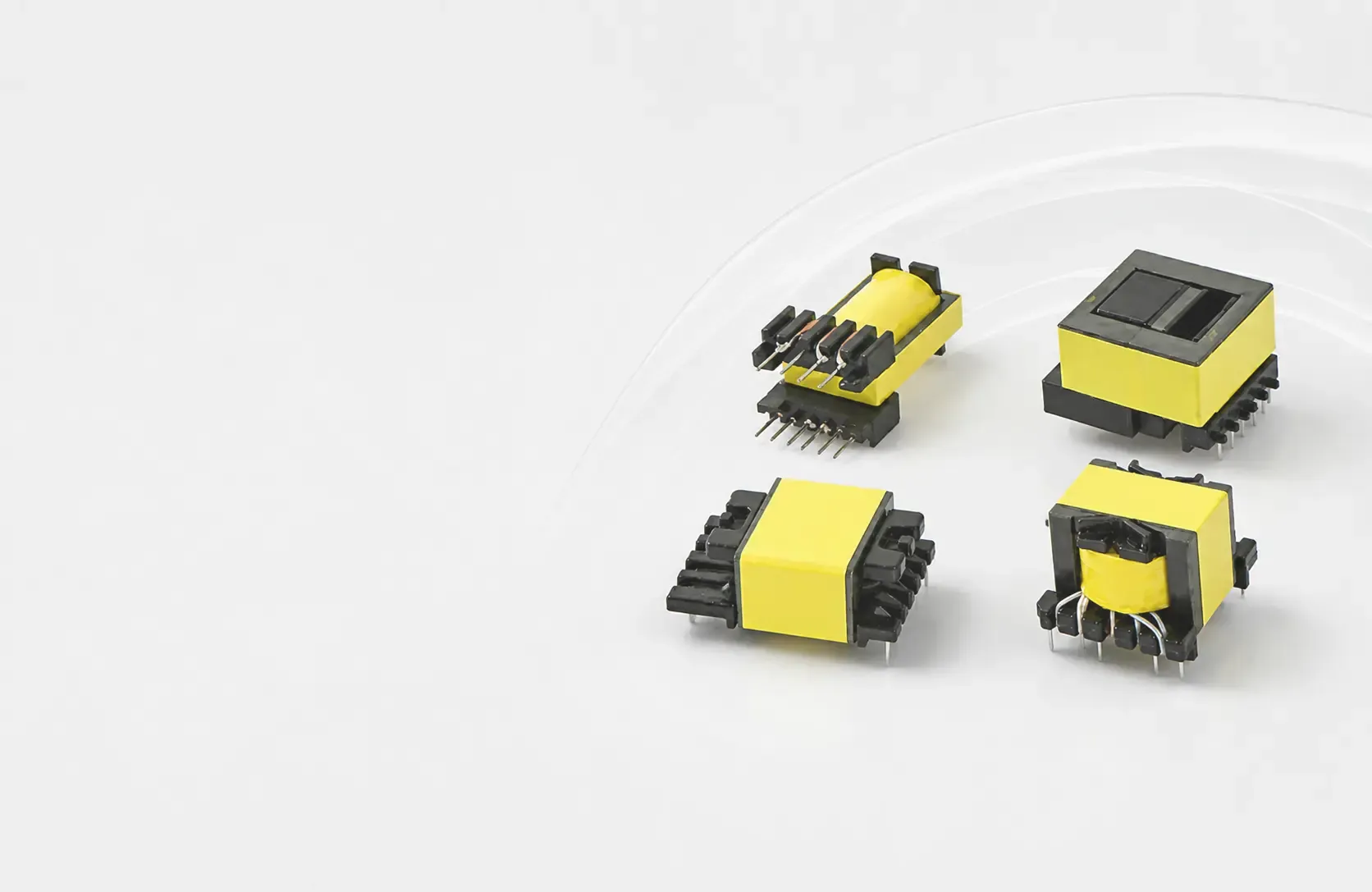
Selecting an SMD common mode choke supplier is not simply a matter of finding the smallest package or the highest published impedance. OEM engineers and sourcing teams should confirm noise-frequency performance, current and thermal limits, land pattern, reflow compatibility, and sample-to-production traceability before approving a component.
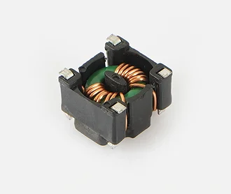
COMMONDE offers an SMD Common Mode Choke for compact PCB noise-suppression applications and discusses OEM/ODM magnetic-component requirements. Its public product page does not provide a verified part-number-level electrical specification, so values such as impedance, rated current, DCR, dimensions, and soldering limits must be confirmed for the actual proposed part.
This guide focuses on supplier qualification and SMT production readiness, rather than repeating a general choke-selection tutorial or a construction comparison.
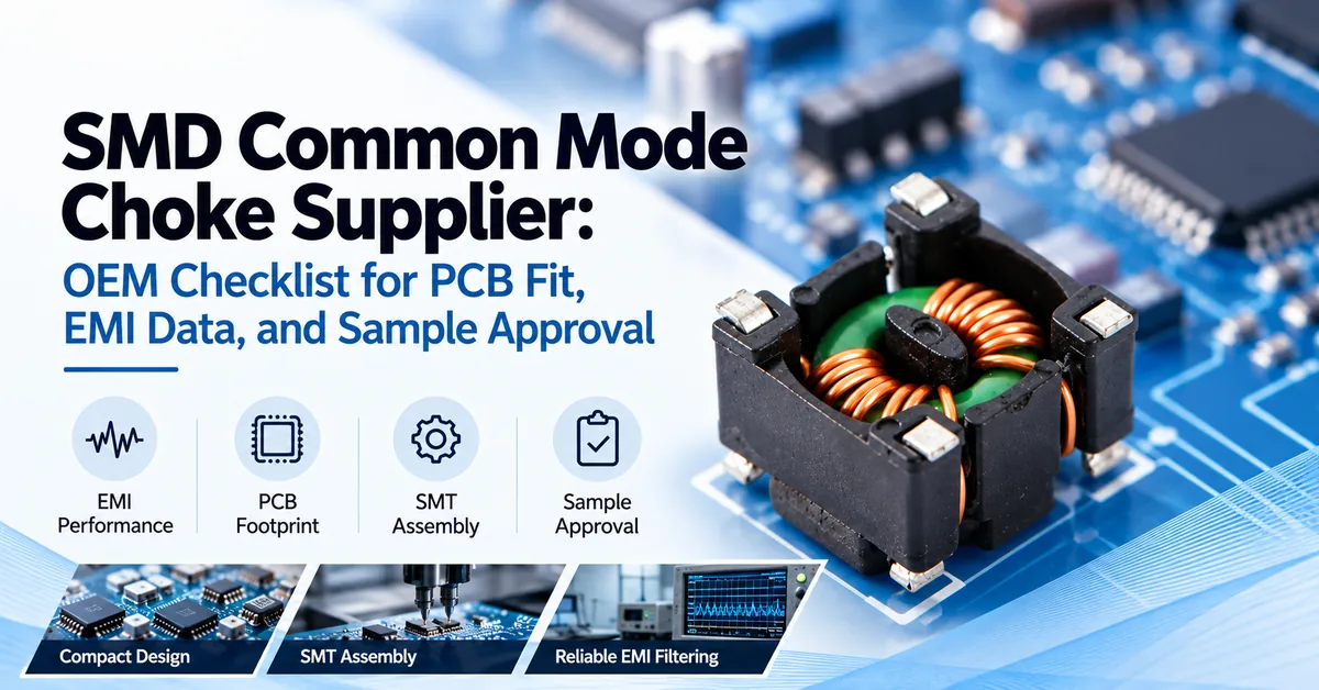
What Does an OEM Need From an SMD Common Mode Choke Supplier?
A qualified supplier should help the buyer answer five questions:
-
Electrical fit: Will the part attenuate common-mode noise in the problematic frequency band without unacceptable losses to the wanted signal or power path?
-
Mechanical fit: Does the approved package fit the board footprint, height envelope, and terminal layout?
-
Assembly fit: Can the component be placed, soldered, inspected, and packaged within the EMS production process?
-
Evidence: Are drawings, electrical curves, inspection criteria, and relevant compliance documents tied to the quoted part?
-
Supply continuity: Can the approved construction and test conditions be controlled from prototypes through production lots?
These checks matter most to power-supply OEMs, industrial controller manufacturers, communication-equipment designers, and electronics manufacturing services (EMS) companies. An SMD part is not automatically appropriate for mains-connected safety isolation, high-voltage input filters, or every high-speed signal interface. Those designs require a separate electrical and safety review.
Why an SMD Common Mode Choke Needs Application-Specific Selection
A common-mode choke contains magnetically coupled conductors. Normal differential current tends to produce opposing flux, while common-mode interference produces reinforcing flux and encounters greater impedance. The part can therefore reduce unwanted noise shared by paired conductors, but it is not a direct substitute for a differential-mode power inductor.
Surface-mount construction is attractive when PCB space, low height, and automated assembly matter. However, a small outline does not prove good filtering in your actual circuit. Frequency response, parasitic capacitance, current, neighboring components, and PCB return paths all influence results.
| Application context | Main purchasing question | Validation priority |
|---|---|---|
| Compact DC power input on an embedded PCB | Is common-mode impedance sufficient at the measured noise frequencies? | Impedance curve, current, DCR, temperature rise |
| Industrial controller supply rail | Can the part fit the crowded board and operate near heat-generating devices? | Footprint, thermal margin, system EMI test |
| Communication equipment interface | Is the filter suitable for the actual signal standard and data rate? | Differential insertion loss, eye diagram where relevant, common-mode rejection |
| High-volume SMT assembly | Will the part arrive in a packaging and termination format compatible with the line? | Land pattern, reflow guidance, reel orientation, solderability |
For related installation contexts, explore COMMONDE's Industrial Automation and Communication Equipment application pages. These are application discussions, not certifications of a particular SMD model.
Technical Specification Checklist Before Requesting Quotes
A comparison becomes meaningful only when every SMD common mode choke supplier is evaluating the same circuit conditions. Request a drawing and specification for a specific proposed part—not merely a photograph or broad series description.
| Parameter or document | What to request | Why an OEM needs it |
|---|---|---|
| Manufacturer part number | Exact ordering code and revision | Prevents approval of an unidentified variant |
| Intended line function | Power line or specific differential signal interface | Determines required electrical checks |
| Common-mode impedance | Curve or values at specified frequencies and test conditions | Identifies performance near the noise band |
| Common-mode inductance | Measurement frequency, connection, tolerance | Supports consistent supplier comparisons |
| Rated current | Continuous rating and stated thermal conditions | Establishes current-handling limits |
| DCR | Maximum resistance per winding and measurement conditions | Helps assess voltage drop and copper heating |
| Differential-mode behavior | Insertion loss or applicable differential characteristics | Protects signal integrity where relevant |
| Temperature conditions | Operating range, derating, test environment | Addresses enclosure and board hot spots |
| Mechanical drawing | Length, width, height, terminals, tolerances | Confirms board and enclosure compatibility |
| PCB land pattern | Recommended pads, pin numbering and orientation | Reduces footprint and assembly errors |
| Assembly specification | Reflow limits, solderability, packaging format | Checks SMT manufacturing compatibility |
| Quality evidence | Relevant inspection plan, traceability and declarations | Supports sample approval and repeat procurement |
1. Compare Impedance at the Noise Frequency—Not at a Convenient Frequency
A single impedance value can conceal a poor match. Ask for the impedance-versus-frequency response in the band identified by your EMI measurements. Equivalent-looking parts can differ because of winding geometry, core properties, parasitic capacitance, and test fixture.
As independent technical reference points, TDK Product Center's common-mode-filter selection guidance and Coilcraft's A Guide to Understanding Common Mode Chokes both emphasize frequency-specific impedance and current capability. These are general selection principles; they do not establish the performance of an untested COMMONDE part.
2. Confirm Rated Current, DCR, and the Actual Thermal Environment
Copper loss rises with the square of current: P ≈ I²R for the relevant winding under DC or low-frequency conditions. Higher DCR may mean greater voltage drop and self-heating. The permissible current also depends on ambient temperature, board copper, airflow, neighboring heat sources, and the supplier's stated rating conditions.
Request per-winding resistance and relevant worst-case operating limits. Do not assume the nominal rating guarantees acceptable performance inside a sealed enclosure.
3. Check PCB Footprint and SMT Assembly Constraints
An SMD part can be electrically suitable and still fail your production handover. Confirm terminal pitch, component height, land pattern, placement orientation, pick-and-place compatibility, and the accepted soldering profile.
Ask whether tape-and-reel packaging, carrier-tape orientation, reel quantities, and solderability data are available for the proposed part. Do not assume a specific package format or moisture classification without documented confirmation.
4. Separate Signal-Line and Power-Line Qualification
An SMD filter on a high-speed differential interface must preserve the wanted signal; common-mode impedance alone is not enough. Request differential insertion loss or signal-integrity measurements appropriate to the interface. For a power rail, current capability, DCR, voltage conditions, and heat may dominate.
A supplier serving one category should not automatically be treated as qualified for the other.
Compare Three Sourcing Routes Before Freezing the BOM
The table below compares approval routes, not verified COMMONDE model specifications. No complete public part-number comparison is available for the featured SMD product.
| Sourcing route | Potential advantage | Main risk | Best next step |
|---|---|---|---|
| Existing catalog SMD part | Less engineering change if specifications match | Missing curve, footprint, or thermal evidence | Request exact datasheet and evaluation samples |
| Form-fit alternative SMD part | May reduce redesign effort | Matching size does not guarantee matching EMI or solder behavior | Run an electrical, layout, and assembly comparison |
| Custom or adjusted SMD solution, if feasible | Potentially addresses application-specific constraints | Tooling, qualification, MOQ, or lead-time changes | Submit complete RFQ and confirm feasibility first |
Buyers comparing SMD against larger constructions can also read COMMONDE's SMD vs Toroidal vs Flat Wire Common Mode Chokes. This article instead addresses how to qualify the SMD supplier and approved part for production.
Manufacturing, Materials, and Quality: What Can Be Verified?
Core formulation, winding arrangement, encapsulation, and termination finish can affect performance and repeatability. Yet appearance alone does not establish the precise magnetic material, internal coupled-winding design, or reliability rating. Ask the supplier to identify the materials and controls applicable to the quoted part.
COMMONDE describes standard magnetic-component supply, OEM/ODM discussions, and production activities such as winding, forming, and testing on its About Us page. Its site also describes incoming, in-process, final, and outgoing quality checks. These company-level statements should be backed by part-specific inspection criteria before an OEM accepts a particular SMD component.
For an SMT purchase, request confirmation of:
-
Incoming material and termination controls.
-
Winding integrity, continuity, and resistance checks.
-
Impedance or inductance testing at defined conditions.
-
Dimensional tolerances and terminal coplanarity where applicable.
-
Solderability, packing, lot marking, and handling instructions.
-
Traceability and how engineering changes are communicated.
Ask for documentation appropriate to your application. An ISO 9001 management-system certificate is not proof that every component has an independent product approval. RoHS or REACH declarations must be checked against the material and part in question; automotive or other industry qualifications must not be assumed.
Sample Approval: A Five-Gate Plan for OEM and EMS Teams
An SMD common mode choke supplier should support a repeatable approval path, not just ship samples that look right.
Gate 1 — Document review. Match the quotation, ordering code, datasheet, drawing, pinout, and sample labels. Record any information not yet supplied.
Gate 2 — Bench electrical verification. Measure DCR, continuity, and frequency response under documented conditions. Compare with the supplier's report using compatible fixtures and connection methods. Include insulation-related tests only where applicable and properly specified.
Gate 3 — SMT build check. Assemble a representative batch using the intended stencil, placement program, reflow process, and inspection criteria. Look for skew, solder defects, clearance issues, or mechanical interference.
Gate 4 — System EMI and thermal validation. Test the assembled product under representative worst-case operating modes and its actual cable, grounding, and enclosure configuration. Where relevant, verify high-speed differential signal integrity.
Gate 5 — Production release. Freeze the approved part number, revision, acceptance limits, packaging, lot-traceability requirements, and change-notification expectations.
This sequence creates a record of what was tested and approved. It does not guarantee EMC compliance merely because a choke is installed.
Example: A Controller Board With a Conducted-Noise Issue
Suppose an industrial controller passes functional bench testing but has a conducted-noise peak when connected to its final cable harness. An engineer should first identify the offending frequency range and the suspected common-mode path. The procurement team can then ask two shortlisted suppliers for frequency-response data, per-winding DCR, a compatible footprint, and sample quantities.
The team would evaluate candidates on the same PCB revision, then repeat emissions and thermal testing with the intended harness. The winner is not necessarily the lowest-priced part or the one with the highest isolated impedance value; it is the approved component that meets the verified system requirements. This is an illustrative workflow, not a claimed COMMONDE customer case.
Cost, Lead Time, and Second-Source Risk
Unit price is only one part of an SMD filter purchasing decision. The larger project cost can come from PCB redesign, failed reflow trials, repeated EMC testing, inconsistent reel orientation, or a component change after customer approval.
A useful supplier comparison separates:
-
Component cost: price at pilot and forecast production volumes.
-
Qualification cost: engineering measurements, assembly trials, and retesting.
-
Delivery conditions: sample availability, MOQ, production lead time, and packaging.
-
Change-control risk: whether materials, terminals, electrical criteria, or manufacturing location may change and how buyers are notified.
COMMONDE discusses standard samples and custom projects, but do not apply any general sample-time statement to your SMD order without a confirmed quotation. For traceable procurement, consult the COMMONDE catalog and available document listings and request the evidence that matches your proposed part.
OEM/ODM RFQ: What to Send COMMONDE
When contacting an SMD common mode choke supplier, a strong RFQ gives the engineer enough context to evaluate the real application.
Include:
-
Device and circuit: end product, power or signal line, connector location, and circuit diagram if available.
-
Electrical requirements: voltage, maximum continuous and transient current, target EMI band, acceptable DCR, and required differential behavior.
-
Mechanical files: board layout, land pattern, maximum height, and available clearance.
-
Environmental conditions: ambient temperature, airflow, duty cycle, and nearby heat sources.
-
Assembly and quality: reflow process, packaging preferences, required declarations, and acceptance tests.
-
Commercial plan: pilot quantity, annual estimate, target schedule, and whether this is an initial design or second-source project.
Explore COMMONDE's SMD Common Mode Choke product page and wider Common Mode Chokes range, then send your design requirements for a part-specific review. Any proposed customization, minimum order quantity, or production schedule should be confirmed during quotation.
Frequently Asked Questions
1. How Do I Identify a Reliable SMD Common Mode Choke Supplier?
Ask for a traceable part number, electrical curve, rated current, DCR, dimensional drawing, soldering guidance, sample test plan, and production change-control process. Validate claims with the actual sample and intended PCB.
2. Is the Highest Impedance SMD Choke Always the Best?
No. Compare impedance in the troublesome frequency range and consider resonance, parasitic effects, operating current, differential signal behavior, and PCB layout.
3. Can I Replace an Existing Part With the Same Package Size?
Only after checking pinout, pad geometry, impedance, DCR, current, thermal behavior, solderability, and system EMI performance. Identical outlines do not establish electrical interchangeability.
4. Are SMD Common Mode Chokes Suitable for High-Speed Data Lines?
Some are designed for specific high-speed interfaces, but suitability depends on differential insertion loss and the signal standard. Do not assume every SMD power-line choke is data-line compatible.
5. What Reflow Information Should I Request?
Ask for an approved temperature profile, peak exposure limits, solderability details, land pattern, packaging orientation, and any moisture-handling instructions that apply to the exact part.
6. Why Does DCR Matter if the Device Is Intended for EMI Suppression?
Normal operating current also flows through the windings. Their resistance affects voltage drop and copper heating, which can limit performance in compact enclosures.
7. Can COMMONDE Discuss Custom SMD Versions?
COMMONDE describes OEM/ODM support for magnetic components. Feasibility for a specific SMD geometry, electrical requirement, termination, and volume must be confirmed with its team.
8. Does an ISO 9001 Certificate Mean the SMD Part Is Certified for My Application?
No. A management-system certificate is different from a product-specific safety, automotive, or environmental declaration. Ask for the applicable document and its scope.
9. What Are the MOQ and Sample Lead Time?
These depend on whether the proposed part is standard or custom, available materials, testing, and order volume. Request written, part-specific confirmation rather than assuming a published general lead time applies.
10. What Should I Include in a First RFQ?
Provide the device type, circuit location, noise-frequency range, voltage and current, DCR requirement, PCB footprint, height limit, operating temperature, assembly conditions, sample quantity, and forecast volume.
Conclusion
Choosing an SMD common mode choke supplier requires a clear link between EMI performance, PCB integration, sample approval, and repeatable production. The best purchasing decision comes from verified, part-specific evidence, not a generic impedance claim, attractive package image, or untested replacement promise.
For compact power and communication electronics, COMMONDE can discuss its SMD Common Mode Choke within a broader magnetic-component sourcing project. Contact COMMONDE with your electrical targets, PCB drawing, application conditions, and expected quantities to discuss the suitable part, required documents, and sample-evaluation route before placing an OEM order.