For industrial power equipment manufacturers, finding a reliable common mode choke manufacturer involves more than selecting a component with a suitable inductance value. The real challenge is translating electromagnetic interference (EMI) requirements into a magnetic component that can be manufactured consistently, installed correctly, and validated in the final electrical system.
The most effective sourcing approach starts with the application, not the component catalog. OEM engineers should identify the common-mode noise problem, define electrical and mechanical requirements, evaluate possible winding structures, and agree on manufacturing and testing conditions before approving production.
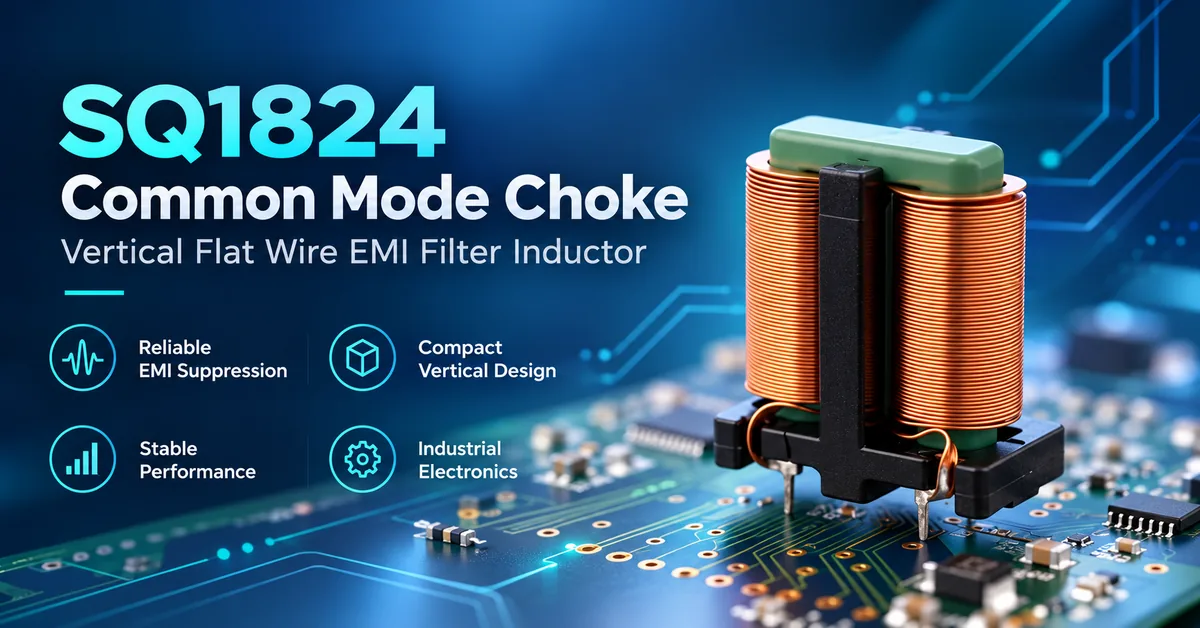
COMMONDE, a magnetic components manufacturer based in Ningbo, China, offers common mode chokes alongside inductors, high-frequency transformers, and ferrite cores. Its product range includes flat-wire, square, multi-chamber bobbin, and SMD common mode choke constructions, with OEM/ODM discussions for application-specific requirements.
This article explains how industrial power OEMs can work with a manufacturer to develop practical EMI filtering specifications, reduce engineering uncertainty, and establish a more reliable procurement process.
Why Industrial Power OEMs Need Application-Specific Common Mode Chokes
Industrial power systems generate electromagnetic noise through high-frequency switching, parasitic coupling, and interactions between power electronics, cables, and grounding structures.
Common-mode interference appears when unwanted currents flow in the same direction along multiple conductors relative to a common reference.
A common mode choke uses magnetically coupled windings to present increased impedance to these interference currents while allowing the intended differential current to pass with comparatively low magnetic opposition.
However, effective filtering depends on more than the magnetic component itself.
Its performance is influenced by:
-
Noise frequency and source impedance
-
Magnetic core material and winding geometry
-
Rated current and DC resistance
-
Parasitic capacitance and leakage inductance
-
PCB layout and cable routing
-
Grounding and filter capacitor arrangement
-
Ambient temperature and thermal conditions
The objective is not to achieve the highest possible inductance. It is to obtain an appropriate impedance response while maintaining acceptable electrical, thermal, mechanical, and manufacturing characteristics.
When Is a Custom Common Mode Choke Worth Considering?
A custom design may be appropriate when an existing component cannot satisfy the required combination of filtering performance, mounting dimensions, current handling, or insulation constraints.
For example, an industrial power converter may have adequate PCB space but require a specific terminal arrangement, while another design may prioritize low winding resistance and limited component height.
The manufacturer must evaluate these requirements together because improvements in one characteristic may introduce compromises elsewhere.
Which Buyers Benefit From a Common Mode Choke Manufacturer?
Different purchasing organizations evaluate magnetic components according to different technical and commercial objectives.
| B2B customer | Typical equipment | Main sourcing requirements |
|---|---|---|
| Industrial power supply OEM | AC/DC power supplies, DC power modules | EMI performance, current rating, thermal stability |
| Solar inverter manufacturer | Inverter power conversion equipment | Conducted-noise suppression, mechanical integration, operating temperature |
| EV charging equipment manufacturer | Charging power modules and control electronics | Current handling, insulation requirements, EMC validation |
| Energy storage equipment OEM | PCS equipment and conversion modules | Filtering performance, thermal management, long-term component availability |
| Industrial automation manufacturer | Motor controllers, drives, control power supplies | EMI control, stable operation, dimensional consistency |
| EMS / PCBA manufacturer | Contract electronic assemblies | Footprint compatibility, solderability, quality documentation |
| Component distributor | Industrial magnetic-component sourcing | Product identification, documentation, repeat ordering |
These applications require different electrical and qualification conditions.
A product suitable for a low-voltage control board should not automatically be selected for a mains-connected or high-voltage power stage.
How to Translate EMI Problems Into Manufacturing Specifications
Before requesting a custom common mode choke, engineers should determine what the filter must accomplish.
A practical approach involves four steps.
Step 1: Identify the Interference Mode
Confirm whether the unwanted noise is primarily common-mode or differential-mode.
A common mode choke targets common-mode interference. It should not be expected to solve every differential-mode ripple or switching-noise problem.
Measurements should distinguish the interfering current paths where practical.
Step 2: Identify the Problematic Frequency Range
The designer should provide the frequency range requiring attenuation.
A single nominal inductance value cannot fully describe high-frequency performance because parasitic capacitance, material losses, and resonance influence the impedance curve.
A manufacturer should therefore be asked for impedance-versus-frequency information appropriate to the intended application.
Step 3: Define Electrical Operating Limits
The engineering specification should identify:
-
Continuous and transient operating current
-
Nominal and maximum working voltage
-
Maximum acceptable winding resistance
-
Operating temperature and cooling conditions
-
Required common-mode impedance
-
Relevant insulation and spacing requirements
-
Mechanical and PCB mounting constraints
These inputs help determine which construction is realistic.
Step 4: Establish System-Level Validation Conditions
A choke is only one element of an EMI filtering system.
Final attenuation depends on the source, load, cables, filter capacitors, layout, and grounding arrangements.
Therefore, the selected component must be evaluated in the actual equipment configuration.
A common mode choke does not independently guarantee that equipment will pass an EMC test.
Technical Specification Checklist for Custom Common Mode Chokes
An effective RFQ should contain measurable requirements rather than general descriptions such as "high inductance" or "excellent EMI suppression."
| Parameter | What OEM buyers should specify | Why it matters |
|---|---|---|
| Common-mode impedance | Required frequency range and target impedance characteristics | Establishes filtering objectives |
| Common-mode inductance | Nominal value, tolerance, measurement frequency and connection | Supports magnetic design and verification |
| Rated current | Continuous current and relevant rating conditions | Helps determine conductor size and thermal limits |
| DC resistance | Maximum acceptable resistance per winding | Controls voltage drop and copper losses |
| Operating voltage | Maximum line voltage and applicable safety conditions | Guides electrical and insulation design |
| Leakage inductance | Relevant limits or intended differential-mode function | Affects differential-mode behavior |
| Magnetic material | Required characteristics or approved material grades | Influences frequency response and thermal performance |
| Operating temperature | Ambient range, hot spots, cooling conditions | Determines thermal design margin |
| Mechanical dimensions | Length, width, height, terminal position | Ensures compatibility with the PCB or equipment |
| Mounting method | SMD, through-hole, or other approved structure | Defines assembly requirements |
| Insulation requirements | Applicable dielectric, spacing and material criteria | Supports electrical safety evaluation |
| Quality requirements | Test methods, acceptance criteria, documentation | Supports repeatable manufacturing |
This is a specification-development checklist, not a published electrical rating table for a particular COMMONDE model. Actual values must be confirmed against the proposed component's technical documents.
Why Rated Current and DCR Must Be Evaluated Together
A common mode choke carries the normal operating current through its windings.
The approximate DC resistive loss in an individual winding is:
P = I²R
where I represents winding current and R is the applicable winding resistance.
Higher resistance can increase heating and voltage drop.
However, lower DCR does not automatically produce a better overall filter. Conductor dimensions, winding geometry, magnetic properties, parasitic capacitance, and package size must be considered together.
For industrial equipment, buyers should evaluate worst-case operating current and actual thermal conditions instead of relying only on nominal ratings.
Common Mode Choke Construction Options for OEM Power Systems
The manufacturing structure influences electrical characteristics, mounting methods, cost, and production complexity.
COMMONDE offers several product families that can provide starting points for engineering discussions.
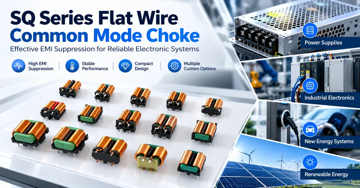
1. Flat-Wire Common Mode Chokes
Flat-wire designs use rectangular conductors rather than conventional round magnet wire.
They may offer useful winding-space and conductor-geometry options, particularly in power electronics where current handling and resistance are important considerations.
However, flat-wire construction also requires attention to conductor forming, bend radius, insulation integrity, termination quality, and parasitic characteristics.
Explore the SQ Flat Wire Common Mode Choke Inductor.
2. Multi-Chamber Bobbin Common Mode Chokes
Multi-chamber designs use separated winding areas within a supporting bobbin structure.
This arrangement can help organize conductors and provide controlled mechanical separation.
For applications with insulation requirements, the actual spacing, material properties, and electrical ratings must be verified rather than inferred from the number of winding chambers.
Explore the Multi-Chamber Bobbins Common Mode Choke.
3. Square Common Mode Chokes
Square or rectangular magnetic assemblies provide another option for PCB-integrated filtering.
Potential engineering considerations include package geometry, winding arrangement, terminal positioning, and mechanical compatibility.
The actual filtering function and electrical characteristics must be confirmed for the selected part.
Explore the Square Common Mode Choke.
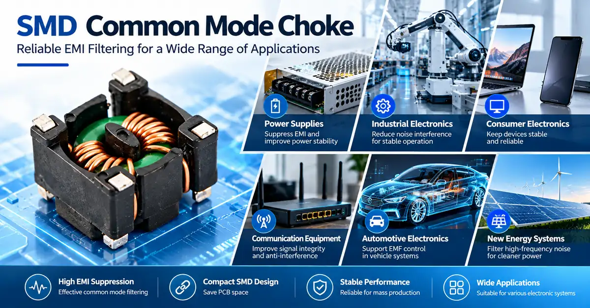
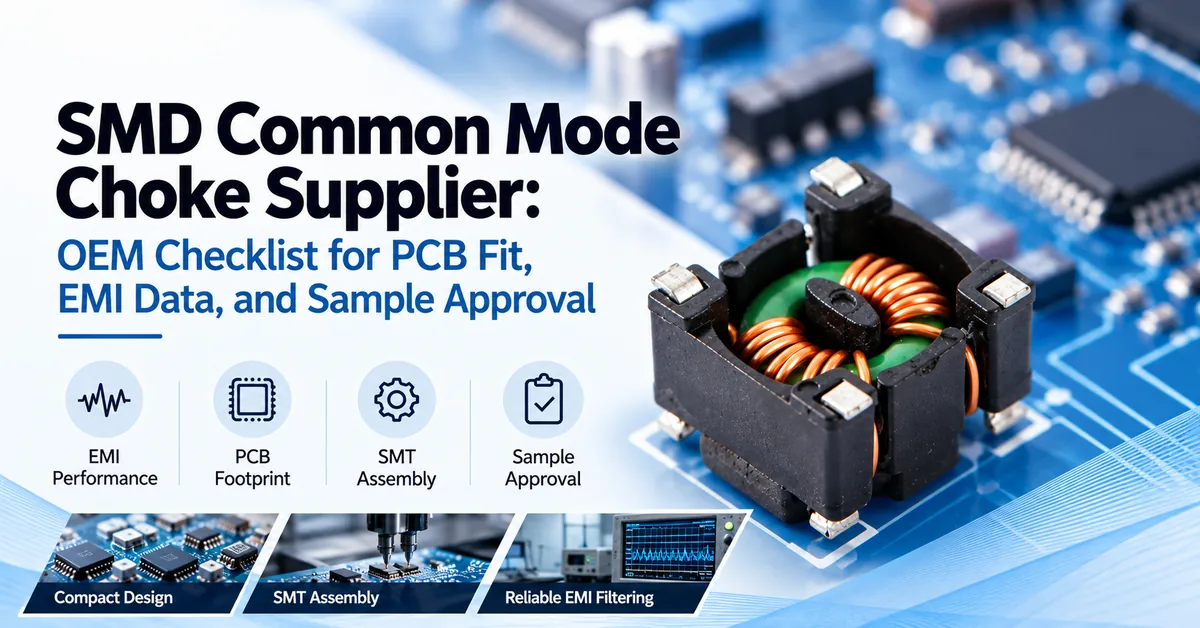
4. SMD Common Mode Chokes
Surface-mount versions are relevant where low component height, PCB density, and automated SMT assembly are important.
Unlike some larger through-hole constructions, SMD designs must be evaluated against footprint dimensions, termination geometry, soldering conditions, and the intended electrical application.
Explore the SMD Common Mode Choke.
Construction Comparison for OEM Projects
| Construction | Design consideration | Manufacturing consideration | Typical sourcing priority |
|---|---|---|---|
| Flat wire | Conductor geometry, resistance, magnetic coupling | Wire forming, insulation, termination | Power electronics requiring specific current and space characteristics |
| Multi-chamber bobbin | Winding separation, spacing, magnetic behavior | Bobbin accuracy, winding placement | Controlled winding arrangement and mechanical requirements |
| Square construction | Package fit, magnetic geometry, PCB integration | Winding consistency, dimensional control | Defined board-mounted magnetic assemblies |
| SMD construction | Miniaturization, impedance response, thermal limits | Terminal geometry, solderability, SMT packaging | Compact electronic boards and automated assembly |
The table compares product constructions, not verified electrical performance rankings.
For further structural differences, see SMD vs Toroidal vs Flat Wire Common Mode Chokes.
How Magnetic Materials and Winding Design Affect Performance
Material and winding selection are central to custom common mode choke manufacturing.
Magnetic Core Materials
Ferrite materials are widely used in EMI suppression because suitable grades can provide useful permeability and frequency-dependent impedance characteristics.
However, magnetic properties differ between formulations.
Engineers should evaluate relevant permeability, frequency response, saturation behavior, temperature sensitivity, and material-loss characteristics.
TDK Electronics' Ferrites and Accessories: Application Notes explains the current-compensated winding principle and the importance of frequency-dependent magnetic properties in common-mode EMI applications.
These are general engineering principles, not verified specifications for a particular COMMONDE product.
Winding Configuration
Winding geometry affects magnetic coupling, leakage inductance, and parasitic capacitance.
Strong magnetic coupling generally helps reduce differential-mode inductance, while a particular filter design may deliberately use some differential-mode impedance.
The appropriate construction depends on the line function.
For high-speed data interfaces, differential signal integrity can be especially important. For many industrial power lines, resistance, temperature rise, insulation, and conducted EMI may be more significant.
Coilcraft's Common Mode Filter Design Guide describes how coupled windings and leakage inductance influence filter behavior.
A custom common mode choke manufacturer should evaluate these trade-offs against the specified circuit conditions.
Manufacturing Process: From Approved Design to Production
A representative manufacturing process for wound common mode chokes includes several controlled stages.
The exact sequence depends on the magnetic construction and must be confirmed for the selected product.
1. Engineering evaluation
Review the customer's electrical targets, application environment, mechanical drawing, and manufacturing requirements.
2. Material and construction selection
Evaluate suitable magnetic materials, winding arrangements, support components, and terminal configurations.
3. Prototype manufacturing
Prepare samples according to the proposed construction and agreed specifications.
4. Electrical and mechanical testing
Measure relevant characteristics under defined test conditions and inspect the mechanical assembly.
5. Customer validation
Evaluate the samples within the actual equipment, including EMI and thermal behavior where required.
6. Production documentation
Confirm the approved design, material requirements, inspection limits, packaging, and change-control expectations.
7. Batch production and outgoing inspection
Manufacture and inspect parts against the agreed product specification.
COMMONDE discusses automated winding, forming, testing, and OEM/ODM services in its company profile. The machinery, capacity, and process controls applicable to a particular product should be verified during project evaluation.
Quality Control and Compliance Documentation
A manufacturing partner should provide the documentation appropriate to the customer's electrical and procurement requirements.
Important quality-control areas include:
| Quality stage | Typical verification | OEM purchasing value |
|---|---|---|
| Incoming materials | Material identity, core condition, conductor specifications | Reduces material mismatch risk |
| Winding process | Winding arrangement, continuity, insulation condition | Supports production consistency |
| Mechanical assembly | Dimensions, terminals, core integrity | Helps prevent PCB installation problems |
| Electrical inspection | Inductance, DCR, impedance or other specified characteristics | Verifies agreed electrical properties |
| Final inspection | Appearance, labeling, packaging and approved requirements | Supports shipment consistency |
| Traceability | Lot identification and relevant production records | Supports investigation and repeat procurement |
What Certifications Should Buyers Verify?
Depending on the destination market and end-product application, buyers may require quality-system documentation, material compliance declarations, or product-specific electrical safety evidence.
These are different types of documentation.
For example, ISO 9001 certification relates to a quality management system. It does not automatically establish that every common mode choke has independent product safety certification.
Likewise, RoHS declarations, insulation-system information, and dielectric withstand results must be assessed against their actual scope.
Never assume that a product is certified for a particular application based only on the manufacturer's general certificate listing.
Manufacturing Capacity, MOQ, and Lead Time
For overseas OEM procurement, reliable delivery depends on accurate project planning.
Production lead time can be influenced by:
-
Availability of magnetic core materials
-
Winding complexity and component construction
-
Custom tooling or fixtures
-
Sample evaluation and design revisions
-
Required inspection or qualification testing
-
Order quantities and production scheduling
A standard catalog component may require less initial development work than a new custom construction, but the actual delivery schedule must be confirmed.
COMMONDE discusses standard products, custom development, and international order coordination. Specific MOQ, production capacity, sample timing, and delivery commitments should be obtained through a project quotation.
How to Reduce the Total Cost of Common Mode Choke Procurement
The lowest unit price does not necessarily result in the lowest overall project cost.
An unsuitable component may create additional expenses through PCB redesign, EMI retesting, thermal problems, assembly defects, or production interruptions.
OEM purchasing teams should evaluate three cost categories.
Component cost: material selection, winding construction, assembly complexity, and order volume.
Qualification cost: samples, engineering reviews, electrical measurements, EMI testing, and documentation.
Supply-chain cost: packaging, lead-time variation, design changes, quality investigations, and alternative sourcing.
A clear RFQ helps manufacturers provide comparable quotations based on the same requirements.
It also helps engineering and procurement teams avoid approving different technical configurations under apparently similar commercial terms.
OEM/ODM Custom Common Mode Choke Development
For applications where standard components do not meet all requirements, OEM/ODM discussions can address the possibility of customizing the magnetic construction.
Potential design variables include:
-
Magnetic core material and geometry
-
Winding arrangement and conductor size
-
Common-mode impedance characteristics
-
Inductance and electrical tolerances
-
DC resistance and current requirements
-
Terminal spacing and mounting structure
-
Mechanical dimensions and height
-
Insulation and thermal requirements
Not every parameter can be adjusted independently, and not every customization is technically or commercially feasible.
The engineering team should therefore establish which requirements are essential and which allow flexibility.
Common Mode Choke RFQ Checklist
Before contacting a manufacturer, prepare:
-
Equipment type and intended application
-
Circuit diagram or relevant input-filter schematic
-
Operating voltage and current conditions
-
Problematic common-mode noise frequency range
-
Required impedance or inductance characteristics
-
Maximum allowable winding resistance
-
PCB footprint and mechanical dimensions
-
Operating temperature and cooling conditions
-
Applicable inspection and compliance requirements
-
Prototype quantity and expected production volume
For a custom project, contact COMMONDE with your technical requirements so its team can discuss suitable product options and manufacturing feasibility.
Frequently Asked Questions
1. What Does a Common Mode Choke Manufacturer Produce?
A common mode choke manufacturer produces magnetically coupled filtering components designed to suppress common-mode interference in compatible power and signal circuits. Constructions can include SMD, toroidal, square, flat-wire, and bobbin-based designs.
2. How Do I Choose a Common Mode Choke Manufacturer for Industrial Power Equipment?
Evaluate the manufacturer's relevant product range, technical documentation, material and winding capabilities, electrical testing, manufacturing consistency, and ability to discuss your application-specific requirements.
3. Can Common Mode Chokes Be Customized for OEM Applications?
Yes, custom common mode chokes may be developed for specific electrical and mechanical requirements. The available customization options depend on material selection, construction feasibility, manufacturing capability, and order conditions.
4. What Is the Difference Between a Common Mode Choke and a Differential Mode Inductor?
A common mode choke primarily presents impedance to interference currents flowing in the same direction through coupled conductors. A differential-mode inductor is intended to provide inductance in the normal differential current path.
5. Which Common Mode Choke Is Suitable for a Solar Inverter?
The appropriate design depends on the inverter circuit, noise spectrum, current, voltage, thermal environment, and installation requirements. No single construction is suitable for every photovoltaic inverter.
6. Is Flat-Wire Construction Better Than Round-Wire Construction?
Neither is universally better. Flat wire may offer useful conductor geometry for some power applications, while round wire may provide different winding and manufacturing advantages. The final choice requires electrical, thermal, and mechanical evaluation.
7. What Electrical Tests Should Be Required Before Production?
Typical requirements may include inductance, DC resistance, common-mode impedance, continuity, and applicable insulation tests. Test conditions and acceptance limits should be agreed upon for the specific component.
8. Does a Common Mode Choke Guarantee EMC Compliance?
No. EMC performance depends on the entire equipment design, including circuit layout, cables, grounding, filtering, shielding, and operating conditions. Final equipment testing remains necessary.
9. What Determines the MOQ and Lead Time of Custom Common Mode Chokes?
Material availability, winding complexity, custom tooling, qualification needs, and production volume can affect MOQ and lead time. These conditions must be confirmed through a manufacturer quotation.
10. What Information Should I Send When Requesting a Common Mode Choke Quote?
Provide operating voltage and current, EMI frequency targets, required electrical characteristics, mechanical drawings, assembly conditions, relevant compliance requirements, and expected quantities.
Conclusion
Selecting a common mode choke manufacturer for industrial power electronics requires a clear understanding of EMI behavior, magnetic construction, manufacturing limitations, and production requirements.
The most effective OEM sourcing process connects real circuit conditions with measurable electrical specifications, suitable winding structures, documented testing, and reliable manufacturing controls.
Instead of choosing a component based only on inductance, appearance, or price, buyers should evaluate the complete filtering requirement and confirm the design through appropriate sample and system-level testing.
COMMONDE offers multiple common mode choke constructions and discusses OEM/ODM magnetic-component solutions for electronics manufacturers.
Explore the COMMONDE Common Mode Chokes product range or contact COMMONDE to discuss your OEM requirements.
Share your circuit information, EMI targets, mechanical constraints, and expected order quantities to begin a technical discussion about suitable components, customization feasibility, and production planning.