Inductor vs. Common Mode Choke: What’s the Difference?
If you are comparing an inductor vs. common mode choke, the first thing to know is that they are not competing parts so much as different tools for different jobs. Both are magnetically based passive components, both can sit in power or signal paths, and both can look deceptively similar on a drawing. But they solve different problems. One is usually chosen to store energy, shape current, or help with filtering. The other is chosen to suppress noise that rides on multiple conductors at once.
That distinction matters in real hardware. Pick the wrong part and you may still get a circuit that “works” on the bench, yet fails in EMI testing, runs hotter than expected, or behaves poorly under load. For engineers, sourcing managers, and product teams, the decision is less about semantics and more about what the circuit must survive: ripple, switching noise, conducted emissions, load transients, or a very crowded enclosure with too little room for error.
Quick answer: what each part is for
An inductor is typically used to resist changes in current. In practical terms, it can smooth current, store magnetic energy, and form part of filters, converters, resonant networks, and power delivery paths. In a switching supply, for example, the inductor is often a core energy-handling part.
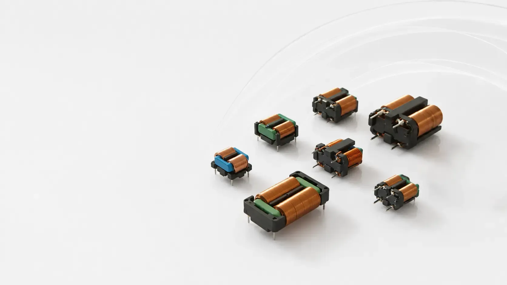
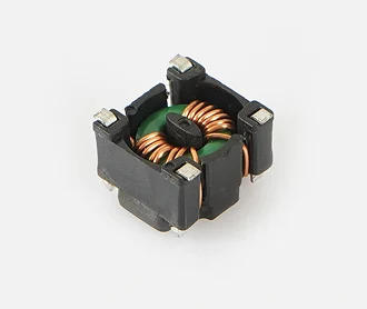
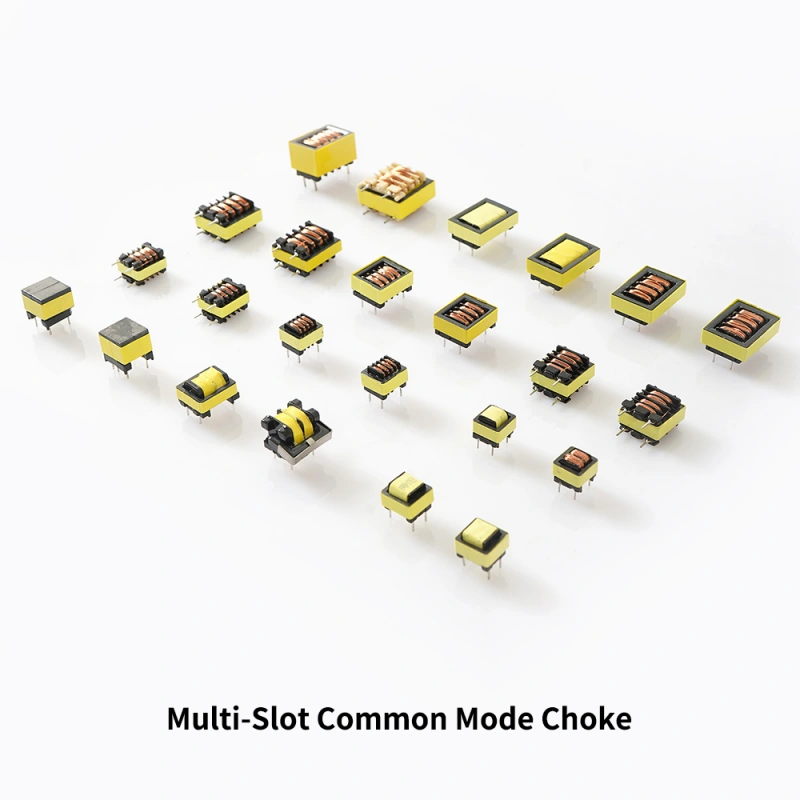
A common mode choke is designed mainly to block common-mode noise while allowing desired current to pass. It uses two windings, usually on a shared magnetic core, so that normal differential current flows through with relatively little opposition, while noise that appears in the same direction on both lines sees high impedance.
That is the cleanest way to frame the difference: an inductor manages current in one path; a common mode choke manages unwanted noise shared across two or more paths.
Why the distinction matters in manufacturing and product design
In a factory environment, design decisions rarely stay at the schematic level. They show up later as assembly yield, enclosure heating, test failures, and field returns. A power inductor can be the right choice for DC-DC conversion in an industrial controller, while a common mode choke may be needed on the mains input or communication line to keep emissions in check.
The parts are sometimes confused because both are wound magnetic components. But if a buyer treats them as interchangeable, the result can be a supply issue or a compliance issue. An inductor may have the current-handling behavior you want, but not the noise suppression you need. A common mode choke may clean up interference, but it is not a substitute for energy storage in a buck converter.
That is the practical decision this article helps with: choosing the right magnetic component for the job before the prototype hardens into a production headache.
How an inductor works
At its core, an inductor is a coil of wire wound around air or a magnetic material. When current flows through it, energy is stored in the magnetic field. When the current changes, the inductor resists that change. That behavior is useful in many ways.
Common uses include:
- Power supply smoothing
- DC-DC conversion
- Signal filtering
- Resonant circuits
- Energy storage in pulse systems
A few practical points matter here. First, inductors are specified by inductance, but that number alone does not tell you whether the part fits the application. You also care about current rating, saturation behavior, DC resistance, size, and thermal performance. Second, in a real industrial product, the layout around the inductor can matter almost as much as the part itself. Long traces, noisy switch nodes, and poor grounding can undo a good choice fast.
How a common mode choke works
A common mode choke typically has two windings on a shared core. The useful trick is that normal differential current in opposite directions tends to cancel the magnetic flux, so the choke does not heavily interfere with the intended signal or power flow. But noise that is common to both lines adds up magnetically, so the choke presents a much higher impedance to it.
That makes common mode chokes especially valuable in:
- AC mains input filtering
- USB and data lines
- Ethernet and communication interfaces
- Motor drive cabling
- Industrial equipment with conducted EMI risk
A buyer should remember one caution: the common mode choke is not a universal noise cure. It works best as part of a filter system that may also include capacitors, grounding strategy, shielding, and cable routing. It is one component in the noise-control chain, not the whole chain.
Inductor vs. common mode choke: the most useful differences
Here is the practical comparison people usually need before ordering parts or approving a design.
1) Job function
An inductor is usually for current shaping and energy storage. A common mode choke is for suppressing common-mode noise.
2) Current behavior
An inductor carries current in a single path and is selected for its ability to handle load and ripple. A common mode choke carries paired currents and is designed so those currents cancel magnetically under normal operation.
3) Circuit placement
Inductors are often found in power conversion stages, filters, and resonant circuits. Common mode chokes are typically placed at interfaces where EMI enters or exits the system.
4) Design criteria
For an inductor, engineers look at inductance, saturation current, DCR, and thermal rise. For a common mode choke, they focus on common-mode impedance, insertion loss, current rating, and insulation or isolation requirements where applicable.
5) Failure mode if misapplied
Using an inductor where a common mode choke is needed can leave the design vulnerable to emissions and noise. Using a common mode choke where an energy-storage inductor is required can create poor regulation, high losses, or outright circuit malfunction.
Selection criteria buyers should not skip
A sourcing team often gets a short component description and a target price, then has to make the call quickly. That is where trouble starts if the specification is too thin.
For inductors, ask:
- What is the required inductance at operating current?
- How much ripple current will the part see?
- What is the saturation current margin?
- Is low DCR important for efficiency?
- What temperature range will the product actually see in service?
For common mode chokes, ask:
- What frequency range needs attenuation?
- Is the application power, signal, or both?
- How much insertion loss can the line tolerate?
- What is the expected continuous current?
- Are there mechanical or insulation constraints tied to the end product?
A small but important aside: in industrial gear, the electromagnetic environment is often harsher than the schematic suggests. Motors, contactors, switching supplies, and long cable runs can all generate noise that makes a “good enough” filter look inadequate in the field.
Common mistakes when specifying these parts
One recurring mistake is assuming a larger inductance value always means a better result. It does not. Too much inductance can slow response, increase loss, or make the circuit unstable.
Another mistake is assuming a common mode choke will solve differential noise. It usually will not. If the noise is traveling on one line against the other, the fix may involve differential filtering, layout changes, or a different suppression strategy.
A third mistake is treating the two parts as if their labels alone tell the whole story. Construction, core material, winding arrangement, and current path matter. That is especially true in compact industrial products, where heat and space are always in conflict.
Where the decision becomes especially important in industrial equipment
Consider an industrial control cabinet, a motor drive, or a pressing machine with a control panel, gauges, and a safety stop circuit. The power stage may need inductive energy handling, while the external wiring may need common-mode suppression to reduce interference and keep the machine stable.
This is where the distinction becomes real rather than academic. A machine can have robust steel construction, an enclosed cabinet, and clearly visible safety hardware, yet still suffer from electrical noise if the magnetic components are chosen casually. That is one reason engineers often review the power path and the I/O path separately. The magnetic part that helps one side of the system may be wrong for the other.
Practical buyer advice for sourcing and design review
If you are reviewing a BOM, do not approve a generic “inductor” or “choke” line item without understanding the function. Ask for the application note, the current waveform, and the filter role. If the supplier cannot explain whether the part is for energy storage or noise suppression, that is a warning sign.
For new product development, it is usually smart to validate both the electrical and thermal behavior early. Magnetic parts can pass a simple continuity check and still underperform under load. A prototype that looks fine during brief testing may reveal noise issues only after hours of operation, after the enclosure warms up, or after it is connected to real plant wiring.
For sourcing, consistency matters too. If a design is sensitive to EMI, do not swap a common mode choke for a similar-looking coil just because the footprint is close. The copper and ferrite may fit, but the function may not.
FAQ
Can an inductor be used as a common mode choke?
Usually no. While both are magnetic components, the winding arrangement and purpose are different. A common mode choke is built to suppress common-mode noise, while an inductor is generally built to manage current and store energy.
Are common mode chokes only for AC power?
No. They are used on many interfaces, including data and communication lines, whenever common-mode noise needs to be reduced.
Which one is more sensitive to saturation?
Both can be affected by magnetic saturation, but the concern shows up differently. For inductors, saturation can quickly undermine power-conversion behavior. For common mode chokes, the issue depends on the balance of currents and the operating conditions.
Do I need both in the same product?
Quite often, yes. A product may need inductors inside its power supply stages and common mode chokes at its external interfaces. They are complementary components, not substitutes.
What to do next
If you are still deciding between an inductor and a common mode choke, start with the circuit’s real job: energy handling or noise suppression. Then check the current waveform, the interface type, the EMI risk, and the thermal envelope. That sequence will usually lead you to the right part faster than comparing datasheets line by line.
For production programs, it is worth confirming the choice with both the design engineer and the supplier before release. A few minutes of review can save a lot of rework later, especially in industrial equipment where electrical noise rarely stays polite.