How Ferrite Core Selection Affects High-Frequency Performance
If you are trying to improve high-frequency behavior in a power supply, filter, transformer, or coil assembly, How Ferrite Core Selection Affects High-Frequency Performance is not a narrow materials question. It is a design decision that shapes loss, temperature rise, noise, and usable bandwidth. Engineers often start with the winding or the circuit, then discover that the ferrite core is quietly setting the ceiling on what the part can really do.
That matters because high-frequency designs leave less room for error. A core that looks fine at low frequency can run hot, shift inductance under bias, or fall apart in efficiency once switching speeds rise. The right ferrite core helps a design stay predictable. The wrong one can force compensation changes, larger heatsinking, or a complete rework of the magnetic stage. For sourcing managers and product teams, that means core selection is not just a technical preference; it affects manufacturability, cost, and field reliability.
What ferrite is actually doing at high frequency
Ferrite is used because it gives magnetic designers a practical way to guide flux without the heavy losses of many metal-based materials at higher frequencies. The material’s composition and formulation influence permeability, saturation behavior, and loss characteristics. In plain terms, one ferrite may support efficient energy transfer in the range your circuit needs, while another starts wasting power as heat long before the product reaches its target operating point.
At high frequency, the two biggest concerns are usually core loss and inductance stability. Core loss rises through a mix of hysteresis and eddy-current effects, and it increases quickly if the material, frequency, flux density, and temperature are not well matched. Inductance also shifts as operating conditions change. That shift can matter more than people expect, because it affects resonance, current ripple, and feedback behavior in tightly controlled power systems.
Why material choice is not interchangeable
There is a tendency, especially in early prototyping, to treat ferrite cores as mostly interchangeable if the shape fits. That is a shortcut worth resisting. Two cores with similar dimensions may behave differently because the material formulation is different. Some ferrites are better suited to power conversion. Others are chosen for EMI suppression, where the useful behavior is not exactly the same as in an energy-storage or transformer application.
The selection question is not simply “which core is best?” It is “best for what operating window?” Frequency, waveform shape, temperature, and DC bias all influence the answer. A core that performs well in a clean lab test may still disappoint in a crowded production enclosure where ambient temperature is higher and the waveform is less ideal. That is one reason design teams should review material curves rather than rely on family names alone.
Key performance factors engineers should compare
Permeability and inductance target
Permeability helps determine how much inductance you get from a given winding count and geometry. Higher permeability can be useful when you want more inductance in a compact space, but it is not automatically better. In some circuits, too much permeability can make the design more sensitive to tolerance stack-up or saturation under load. If the application requires a specific inductance window, the core has to support that value across expected operating conditions, not just at room temperature and small-signal test levels.
Core loss versus frequency
This is usually the first place where a ferrite selection gets confirmed or rejected. Core loss does not rise in a neat straight line, and different materials respond very differently as frequency climbs. For high-frequency performance, designers often look at loss curves at the intended flux density and temperature, not just a headline frequency rating. If the loss data is incomplete, that is a warning sign. You can sometimes compensate with cooling or a different winding strategy, but that adds cost and complexity.
Saturation behavior under load
Saturation is the point at which the core can no longer support additional magnetic flux effectively. In practical terms, once you get close to saturation, inductance drops and the magnetic component can misbehave quickly. In switching applications with DC bias, that risk rises fast. So even if a ferrite has a good low-loss profile, it still has to tolerate the real current profile of the circuit. A core that is efficient but too close to saturation margin is often a false economy.
Temperature stability
Temperature shifts both magnetic behavior and loss. A ferrite that seems ideal at 25°C may drift enough at elevated temperatures to affect regulation or noise performance. That is especially important in enclosed products and industrial equipment, where ambient conditions are less forgiving than bench tests suggest. Buyers should ask whether the operating temperature window matches the application, not just whether the material was tested once under ideal conditions.
Shape and geometry matter more than many teams expect
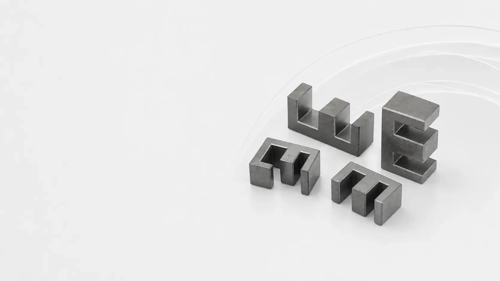
Material selection gets the attention, but geometry often decides whether the part is actually manufacturable. Core shape affects winding window, leakage inductance, thermal path, and assembly effort. Toroids, E-cores, pot cores, and similar forms each bring tradeoffs. A compact geometry may reduce size, but it can complicate winding or make inspection harder. A more open geometry may be easier to assemble, though not always as tight electromagnetically.
In production, these choices reach beyond electrical performance. If the winding process is manual or semi-manual, as it often is in small-part or coil-focused manufacturing, the core shape must work with operator handling. That is where structured assembly workstations, labeled positions, and organized parts storage can help maintain repeatability. A well-run workstation setup does not change magnetic physics, of course, but it does reduce the chance that a good design is spoiled by inconsistent assembly.
Common mistakes when specifying ferrite cores
One common mistake is choosing by size alone. Another is optimizing for low-frequency inductance and forgetting that the real challenge is switching loss at higher frequency. Teams also sometimes overlook the way winding construction interacts with the core. A core that looks excellent on paper may not leave enough room for the conductor arrangement needed to control parasitics.
A more subtle mistake is assuming that one test point proves the design. High-frequency components should be checked across the actual operating range, including temperature extremes and load variation. If the product will be manufactured at scale, the component should also be evaluated for consistency from batch to batch. Ferrite materials can vary enough that a design with little margin becomes awkward very quickly.
Practical buyer advice for sourcing and production teams
If you are sourcing ferrite cores for a high-frequency application, start by aligning electrical requirements with manufacturing realities. Ask for the material data that corresponds to your frequency band, operating temperature, and expected flux density. Then compare geometry options against the winding process you actually plan to use.
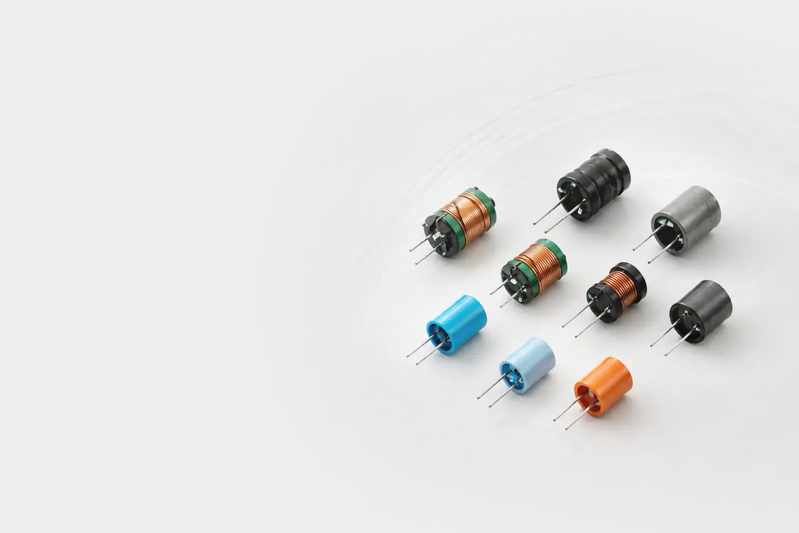
This is where production layout and workstation discipline matter more than many design reviews admit. A modular assembly line with numbered stations, integrated bin storage, and organized operator positions can support repetitive coil handling or inspection tasks more reliably than a loose bench setup. For components as sensitive as ferrite-based assemblies, that kind of flow helps reduce variation in winding count, lead placement, and part handling. In smaller operations, it may be the difference between a stable pilot run and a frustrating stream of rework.
Also ask practical questions early: Can the part be wound without forcing conductor damage? Is there enough clearance for insulation systems? Does the chosen core make automated or semi-automated assembly easier later, even if the first build is manual? Those details are easy to ignore during schematic work and expensive to fix after tooling is in motion.
What to watch during prototyping and validation
Prototype testing should confirm more than whether the part “works.” It should show how the core behaves when the system gets warm, when current rises, and when the waveform is less clean than the simulation assumed. If measurements show unexpected heating or an inductance shift that changes the control loop, the core is telling you something useful. Do not paper over it with compensation changes too quickly.
It is also worth documenting how the winding and core are assembled during the prototype phase. A process that looks acceptable for ten units may reveal handling issues at a hundred. For production teams, that is where a standardized workstation setup and clear station labeling can support traceability and keep the build sequence from drifting.
FAQ: quick answers teams usually need
Is a higher-permeability ferrite always better?
No. It may give you more inductance, but it can also increase sensitivity to saturation, tolerance variation, or design instability.
Why does my ferrite component run hotter at high frequency?
Core loss usually rises with frequency, flux density, and temperature. The material may simply not be matched well to the operating window.
Should I choose the core first or the winding first?
In practice, both should be developed together. Geometry, conductor choice, and core material all influence the final result.
Can a good assembly setup really affect ferrite performance?
It affects the assembled component more than the material itself. But consistent winding, handling, and inspection are essential if you want the design’s electrical performance to hold up in production.
Choosing the core is really choosing the margin
Ferrite core selection affects high-frequency performance because it sets the limits on loss, inductance stability, and thermal behavior. The best choice is not the one with the most impressive material name or the cheapest initial price. It is the one that fits the actual waveform, operating temperature, mechanical format, and assembly method without forcing constant compromises.
For teams moving from bench work to repeatable production, the safest next step is to compare candidate materials against real operating curves, then test them in the same winding and workstation conditions you plan to use in production. If the goal is a stable coil, transformer, or suppression component at high frequency, that disciplined comparison is where the real answer usually shows up.