How to Choose a Common Mode Choke for EMI Filtering
If you are trying to solve conducted noise, radiated noise, or a stubborn EMC failure, How to Choose a Common Mode Choke for EMI Filtering is usually less about picking a part number and more about matching the choke to the real noise problem on the board or harness. That sounds obvious until you are standing in front of a design that passes functional test but fails emissions because of a cable acting like an antenna, or a power rail that looks clean in simulation and ugly on the bench.
A common mode choke is one of those components that can look deceptively simple. Two windings, one magnetic core, and a datasheet full of curves. In practice, the choice affects insertion loss, DC current handling, signal integrity, temperature rise, and even how much rework you may face later if the part is too aggressive or not aggressive enough. The wrong choke can choke the signal path as much as the noise path. The right one can save a redesign.
What a common mode choke is actually doing
A common mode choke is designed to present high impedance to common-mode noise while leaving the desired differential signal or power current relatively undisturbed. That distinction matters. Engineers sometimes reach for a larger impedance number thinking bigger is automatically better, but EMI filtering does not work that neatly.
The useful question is not just “how much impedance does this part have?” It is “at what frequency, with what current, in what circuit topology, and with what parasitics?” A choke that works beautifully on a low-speed power line may be a poor choice for a high-speed data pair. Likewise, a part selected purely on inductance can disappoint once real-world coupling, saturation, and layout effects appear.
For sourcing managers and product teams, the practical decision is whether the choke is the right tool in the first place. Sometimes a ferrite bead, a feedthrough capacitor, improved grounding, or a layout correction does more than adding another magnetic part.
Start with the noise source, not the catalog
Before comparing parts, identify where the noise is coming from and how it is traveling.
Is it conducted noise on a power input? Is it common-mode noise riding on a USB, Ethernet, CAN, RS-485, or display line? Is the problem mainly near-field coupling from a switching stage, motor drive, or fast edge-rate digital section? Those answers determine whether a common mode choke belongs in the circuit at all and where it should sit.
A good rule: place the choke as close as practical to the entry or exit point of the noise path. On external cables, that often means near the connector. On internal harnesses, the choke should intercept the noisy path before it becomes an antenna. Layout matters more than many teams want to admit; a good choke placed badly can become a decorative component.
Key selection criteria that actually matter
Common-mode impedance at the relevant frequency
The headline impedance figure is only useful if it lines up with the offending frequency range. Many EMI problems are not caused by a single narrow tone, but by a band of switching harmonics. Look at the impedance curve, not just the top-line value. A part that peaks at the wrong frequency may do little for your actual emission signature.
Current rating and temperature rise
Current handling is easy to underestimate. Even when the desired differential current is supposed to flow through both windings and cancel magnetically, real circuits are not perfect. Imbalance, offset, and inrush can push the core toward saturation or drive unwanted heating. If the choke runs hot, its impedance may shift and performance can fall off right when you need it.
For industrial or automotive-adjacent hardware, this becomes especially important because vibration, ambient heat, and enclosure restrictions all work against thermal margin.
Differential-mode impact
A common mode choke is intended to leave differential-mode current mostly alone, but no part is ideal. Leakage inductance and winding resistance can affect signal edges, eye diagrams, timing margins, or power conversion efficiency. On high-speed interfaces, that can become the deciding factor. A part that is superb for noise suppression but ruins the signal is not a win.
DC resistance and voltage drop
For power lines, DC resistance matters because every milliohm contributes to loss and voltage drop. On low-voltage rails, that can matter more than people expect. A choke with strong EMI performance but excessive DCR may create thermal and efficiency issues across the whole product.
Package size and mounting style
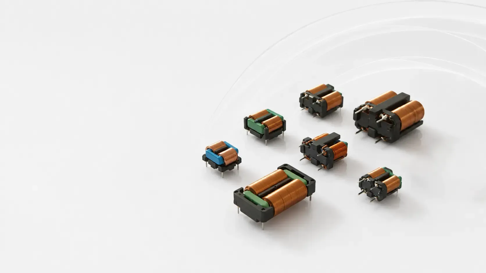
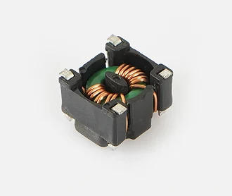
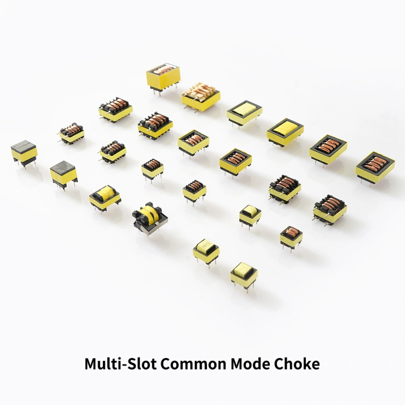
Mechanical fit is not a footnote. The choke has to survive manufacturing, inspection, and field use. Surface-mount parts save space, but larger current applications may require physically larger packages or through-hole styles. If your assembly process is automated, make sure the component is compatible with placement, soldering, and inspection flow. This is where industrial thinking helps: the component must fit the line, not just the schematic.
Choose by application type
Power input filtering
On DC input lines, the priority is usually reducing conducted EMI without sacrificing efficiency or thermal performance. A common mode choke can be useful when noise is returning through both conductors together, especially on external cables. It is less useful if the issue is purely differential ripple from the converter itself.
In these applications, verify the saturation behavior and thermal behavior under real load. A part that looks fine at room temperature on the bench may be marginal inside a sealed enclosure.
High-speed data lines
For USB, Ethernet, LVDS, CAN, or similar interfaces, signal integrity is often the first constraint. The choke must suppress common-mode noise while avoiding excessive insertion loss, skew, or eye closure. In this category, the datasheet curves for differential impedance, insertion loss, and frequency response deserve as much attention as the EMI numbers.
A practical caution: if the interface standard is already tight on margins, a common mode choke should be treated as a controlled intervention, not a default add-on.
Motor and actuator wiring
Motor leads, actuator harnesses, and solenoid wiring can be noisy and can also receive noise from nearby switching circuits. Here, the choke may be part of a broader suppression strategy that includes cable routing, shielding, and suppression at the source. Do not expect a single choke to clean up a poorly routed power harness by itself.
Reference comparison: what to check on the datasheet
When reviewing candidate parts, use the datasheet as a decision tool rather than a marketing sheet.
Look at the impedance curve across frequency, the rated current, the DCR, insulation and dielectric details if relevant, package dimensions, and any differential-mode performance data. If the application is noise-sensitive, pay attention to parasitic capacitance and self-resonant behavior as well. Some parts look strong on paper but taper off at the frequencies that matter most.
It also helps to compare the part under your actual operating conditions. A choke that performs well at low current may not hold the same behavior at higher load or temperature. If you can, test it in the intended board, cable, or harness environment rather than relying only on bench measurements with ideal wiring.
Common mistakes engineers still make
One of the most common mistakes is choosing a choke for the wrong mode of interference. If the problem is differential noise, a common mode choke may not solve it. Another is focusing on maximum impedance without checking the frequency band where the noise exists. A third mistake is ignoring layout and return paths, which can undermine even a carefully selected component.
There is also a procurement-side mistake: treating equivalent-looking parts as interchangeable when the magnetic material, winding structure, or thermal characteristics differ in ways that matter in production. Two parts may fit the same footprint and behave very differently under load. That is where second-source planning should be done carefully, not casually.
Practical buyer advice for sourcing and production teams
If you are sourcing for a platform program, ask for test evidence tied to the application, not just generic compliance claims. You want to know whether the choke was evaluated on the same interface or power profile you are buying for. Ask about packaging consistency, tape-and-reel or bulk handling as needed, and whether the part has any assembly sensitivities that affect automated placement or soldering.
For product teams, involve EMC and manufacturing early. A choke selected late in the cycle can force board changes, connector changes, or a layout reroute. That is expensive. It is often cheaper to reserve space for an EMI filter stage than to discover after pilot build that emissions are failing by a narrow margin.
For engineers working on automated equipment or industrial controls, the same logic applies. Machines with HMI panels, actuators, drives, sensors, and cable bundles can generate plenty of noise, and the filtering decision should be made with both electrical behavior and machine integration in mind. Components are only one layer; assembly quality and harness discipline matter too.
FAQ: quick answers buyers usually need
Is higher impedance always better?
No. Higher impedance can help common-mode noise, but it may also affect signal quality, size, cost, and thermal behavior. Match the part to the noise spectrum and the circuit limits.
Can one choke solve all EMI problems?
Rarely. EMI problems usually involve a combination of source noise, coupling path, and poor return control. The choke is one tool, not a universal fix.
Should I choose by current or by impedance first?
Both matter, but current and thermal limits are often non-negotiable. If the part cannot survive the load, impedance numbers are academic.
Do I need lab testing before final selection?
If the product has any meaningful compliance risk, yes. Bench validation with the final layout, cables, and enclosure is far more valuable than comparing datasheets alone.
What to do next
If your design is at the point where EMI filtering is becoming a schedule risk, build a short shortlist of candidate common mode chokes and test them in the real application. Compare not just emissions reduction, but temperature, signal quality, and production fit. That is the decision that matters.
If you are still early in the design phase, reserve board space and keep the filter strategy flexible. A little planning now can save a painful late-stage board spin later.