Circuit designers and procurement teams often encounter packaging constraints when standard inductive components exceed available vertical clearance or fail to deliver adequate electromagnetic attenuation. Sourcing magnetic assemblies through specialized ODM/OEM channels resolves this challenge by enabling engineering teams to tailor winding structures, slot allocations, and mounting orientations to precise electrical and volumetric envelopes. For dense power electronics, low-profile through-hole wound components provide an effective balance between mechanical stability, creepage distance, and electromagnetic interference (EMI) mitigation.
Product Overview and Mechanical Architecture
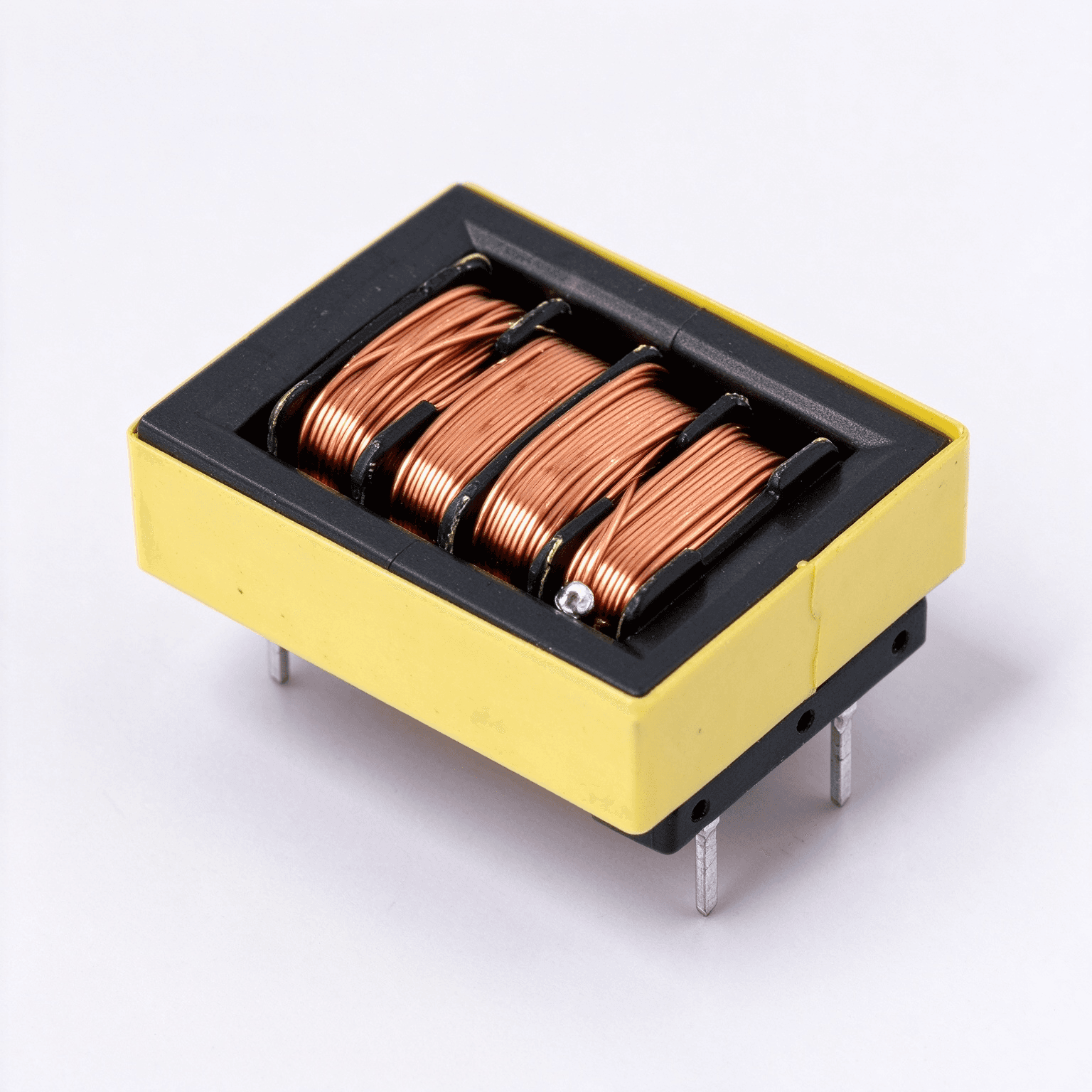
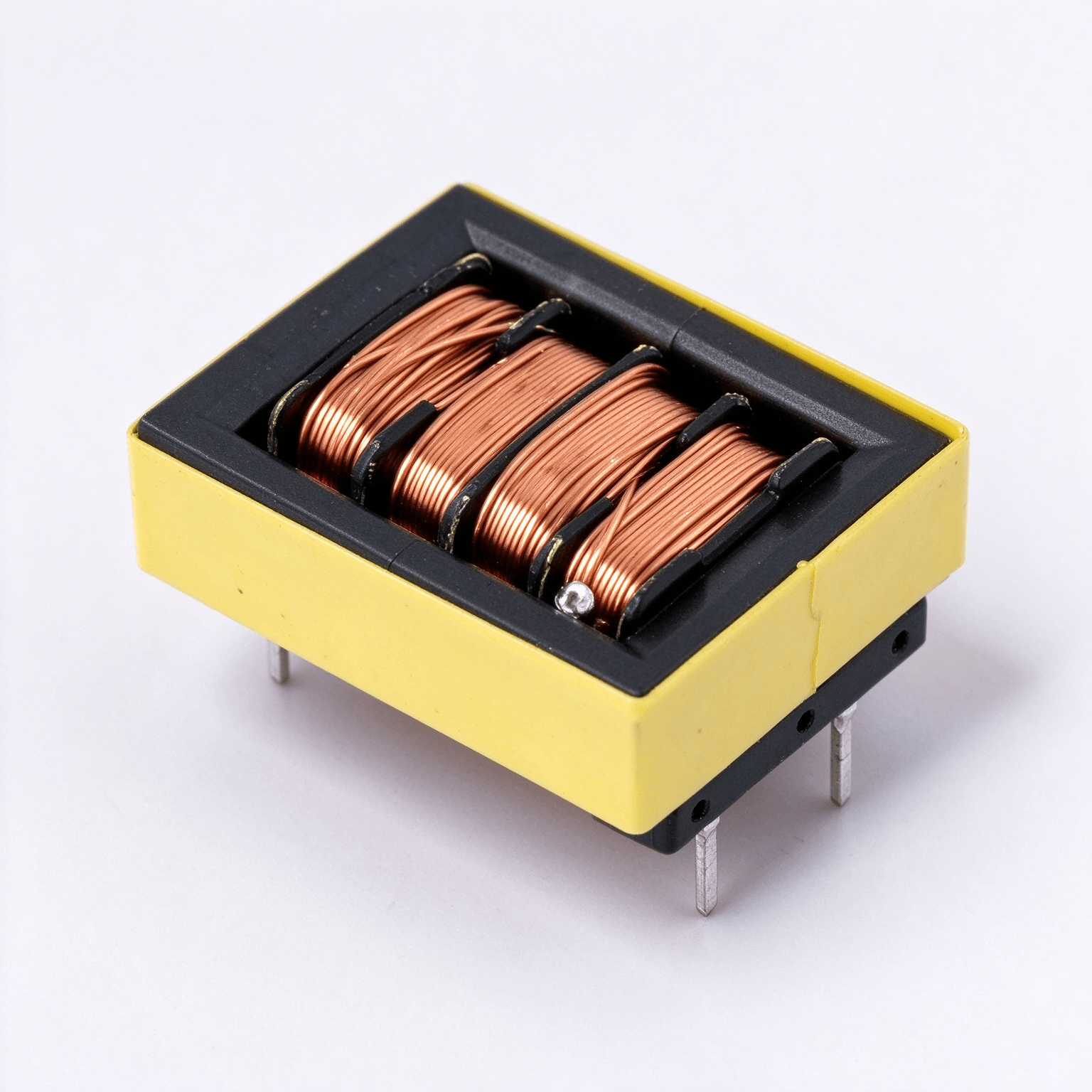
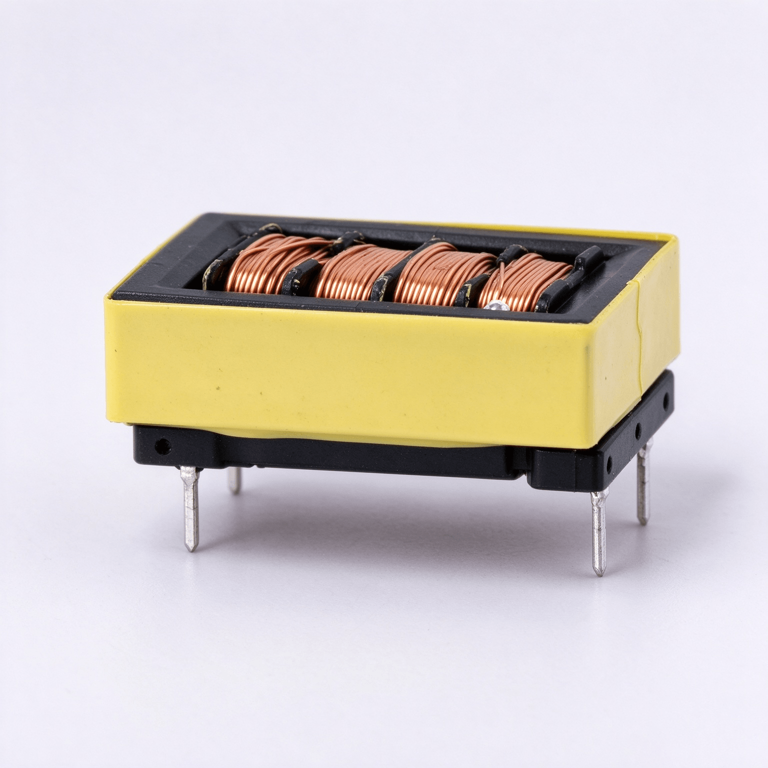
Through-hole wound magnetic components configured in low-profile packages are primarily designed for compact switch-mode conversion systems. The component architecture represented by the EFD1520 Horizontal Four Slot Common Mode Choke with Ferrite Core for Switching Power Supplies and Inverter Equipment addresses vertical height limitations while maintaining multi-winding isolation. Its mechanical structure features a horizontal orientation where the primary magnetic axis rests parallel to the underlying circuit board.
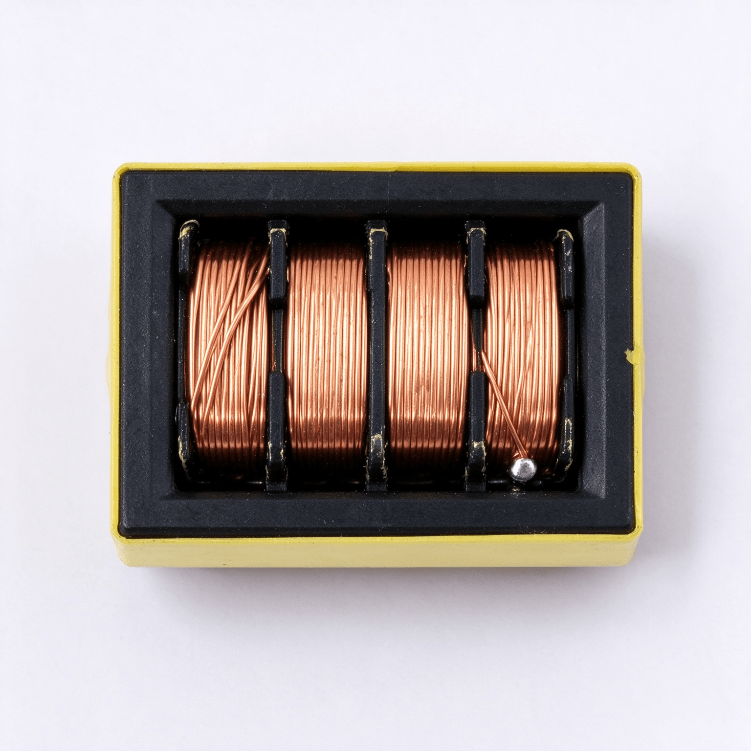
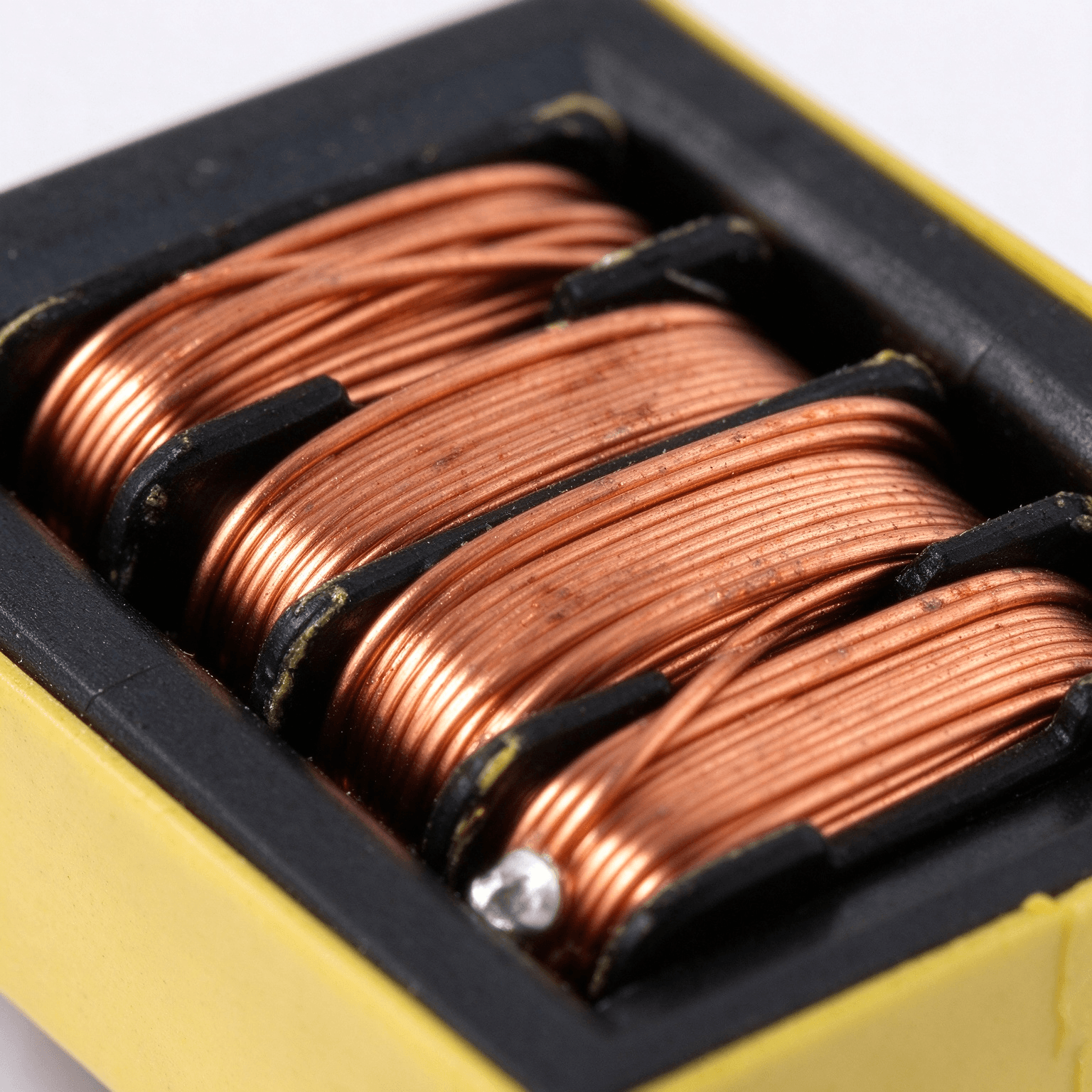
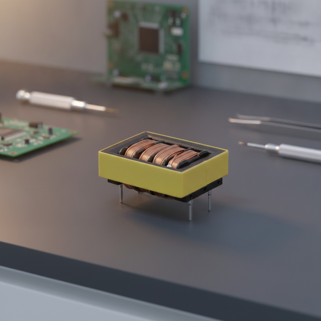
Visual and structural analysis reveals a rectangular assembly consisting of a protective outer housing, a segmented black polymeric bobbin, and multiple parallel sections of tightly wound copper magnet wire. Metallic terminal pins extend downward from the base for through-hole soldering, providing high mechanical anchoring against shock and vibration. The multi-slot division creates physical barriers between winding segments, which assists in maintaining electrical separation and minimizing parasitic capacitance across the component length.
Materials and Construction
Conductor and Insulation
The winding sections utilize enameled copper magnet wire, wrapped with high consistency to prevent turn-to-turn overlap and insulation abrasion. The exposed coil geometry facilitates direct visual quality checks for winding uniformity and enamel integrity prior to circuit board integration.
Structural Housing and Bobbin
A black insulating bobbin forms the core retention structure and defines the slot spacing. Surrounding the perimeter is a yellow polymer housing that acts as a structural shield, protecting the magnet wire from peripheral handling damage. The exact polymer chemistry and flammability ratings are determined according to customer-specific thermal and environmental requirements.
Core Assembly
The magnetic core, enclosed within the bobbin and housing assembly, establishes the closed inductive path. In high-frequency filtering components such as an EFD1520 assembly, ferrite core chemistries—typically manganese-zinc or nickel-zinc formulations—are selected based on target attenuation frequencies, permeability needs, and saturation characteristics.
Functional Capabilities and Engineering Value
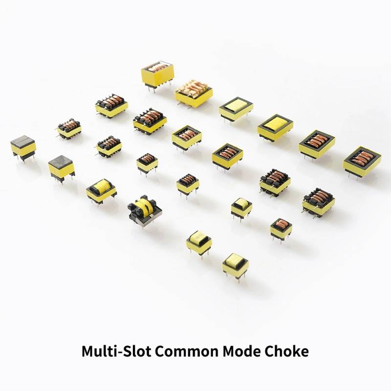
When configured as a common-mode filter, this multi-slot magnetic component presents balanced impedance against high-frequency line noise generated by switching semiconductors. The compartmentalized slot layout offers notable electrical advantages:
- Reduced Parasitic Capacitance: Dividing the winding across multiple slots spreads the voltage gradient and decreases turn-to-turn capacitive coupling, shifting the component self-resonant frequency (SRF) higher into the megahertz spectrum.
- Thermal Dissipation: The horizontal posture and partially exposed winding windows allow natural convection airflow across the copper surface, assisting in thermal management under continuous current loads.
- Vibration Resistance: Multiple through-hole leads and a wide baseline ensure secure placement on printed circuit boards operating in demanding industrial environments.
Application Scenarios
Through-hole horizontal inductors and chokes are deployed across a broad range of medium-to-high frequency power systems:
- Switch-Mode Power Supplies (SMPS): Serving as line-input or intermediate-stage EMI filters to suppress conducted switching transients.
- Inverter Equipment: Mitigating common-mode circulating currents and high dV/dt noise in compact motor drives, solar microinverters, and power optimizers.
- DC-DC Conversion Modules: Providing inductive smoothing and noise separation in telecommunications and server power distribution shelves.
- Battery Chargers and Industrial Controls: Protecting sensitive analog control loops from industrial power-bus disturbances.
Quality Control and Testing Procedures
Reliable production through ODM/OEM lines requires standardized quality validation at multiple assembly stages:
- Dimensional Verification: Confirming lead pitch, standoff clearance, and outer body dimensions to ensure automated or manual PCB insertion compatibility.
- Inductance and DCR Testing: Measuring baseline inductance (L), leakage inductance (Lk), and direct-current resistance (DCR) on four-wire bridges to verify turn accuracy and winding symmetry.
- Dielectric Strength (Hi-Pot): Applying high-voltage test sequences between isolated windings to guarantee insulation integrity under transient overvoltages.
- Solderability Inspection: Evaluating terminal lead finishes to ensure uniform wetting and void-free solder joints during wave or selective soldering processes.
ODM/OEM Customization Guidance
Hardware engineers specifying components within the EFD1520 form factor can adapt several parameters to their circuit requirements. When initiating a build specification, designers should define:
- Winding Schedule: Number of turns per slot, wire gauge, and single- or bifilar-winding arrangements depending on required rated current and choke impedance.
- Core Material Grade: Selection of high-permeability ferrite for low-frequency attenuation or lower-permeability materials for high-frequency noise absorption.
- Pin Configuration: Terminal lead count, diameter, and custom bent-lead options to match proprietary PCB land patterns.
- Environmental Protection: Optional conformal coating, specific varnish impregnations, or high-temperature resin choices to withstand harsh operating atmospheres.
Inquiry and Technical Support
To request technical datasheets, mechanical drawings, or prototype samples built to your circuit parameters, submit your electrical schematics, space envelopes, and target inductance ratings to our engineering team. Custom prototypes and production schedules are established following a comprehensive review of your technical specifications.