EE Core for Transformers, Inductors, and Magnetic Assemblies
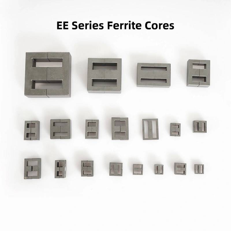
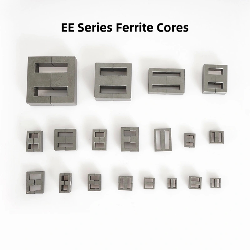
An EE Core is used when a buyer needs a compact magnetic path that can be assembled into transformers, inductors, chokes, and other electronic power components without wasting space or compromising coil placement. In practical terms, this type of core helps engineers build magnetic circuits that guide flux efficiently through a winding window, which supports stable energy transfer and EMI control in power electronics. The family shown here appears to include multiple sizes and matching halves, giving designers flexibility when matching core geometry to power level, frequency, and package constraints.
Product Overview
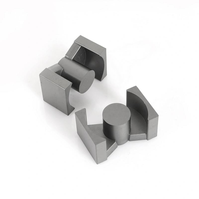
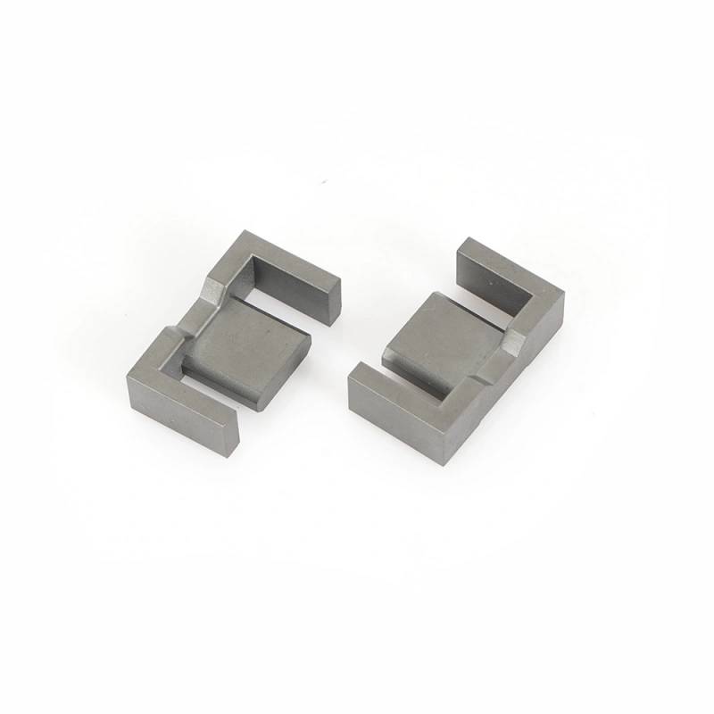
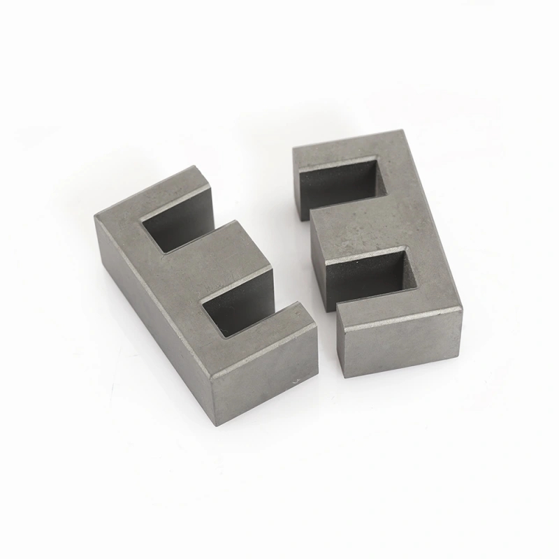
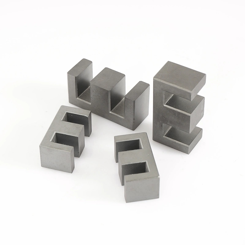
EE-style ferrite cores are a common building block in electrical and electronic assemblies. Their shape provides two outer legs and a center leg, creating a winding window that is easy to coil and assemble. When two matching pieces are brought together, they form a closed magnetic path. That geometry is useful in switch-mode power supplies, DC-DC converters, filters, and signal isolation components.
From the visible product data, the cores appear to be gray ferrite ceramic parts with a matte, uncoated finish. The family includes several sizes, which suggests a standardized range rather than a single custom part. The surfaces look clean and the edges are sharply formed, indicating controlled manufacturing and repeatable shaping.
What Problems This Core Geometry Solves
Buyers often choose an EE Core when they need to manage magnetic flux in a limited footprint. A poor core choice can lead to oversized winding windows, inefficient energy transfer, higher losses, or difficulty fitting the part into a compact enclosure. The EE form addresses those issues by balancing usable coil space with a straightforward assembly structure.
For engineers, the shape also simplifies layout. The central leg offers a predictable winding area, while the outer legs help close the flux loop. This makes the core family suitable for designs that need standardization across several power ratings or product variants.
Key Specifications and Capabilities
Visible Design Features
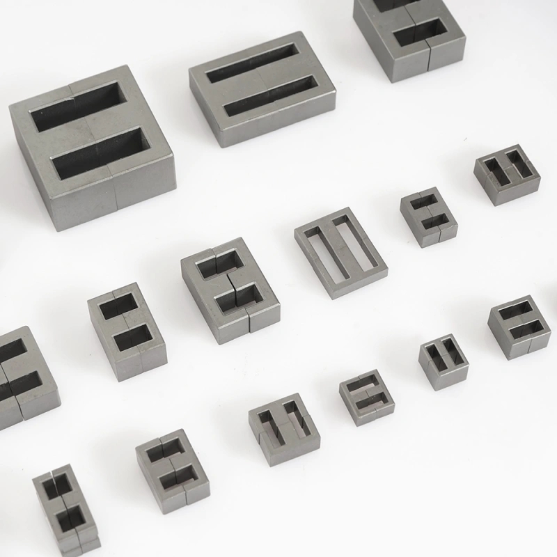
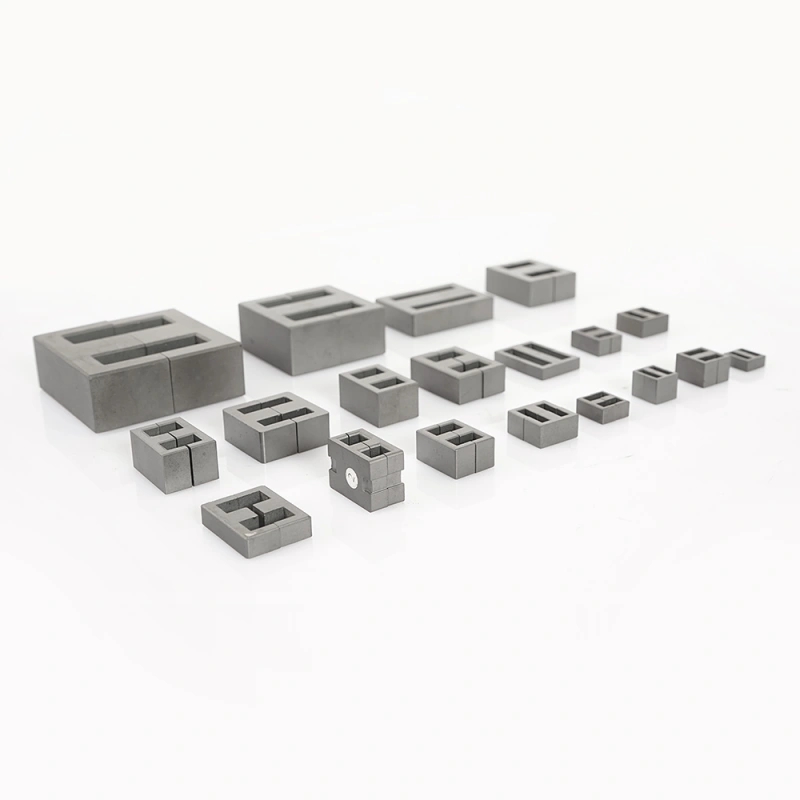
The visible parts show a rectangular, symmetric EE-style structure with two central legs and outer yoke sections. Several sizes are present, which is helpful when selecting a core for a specific transformer or inductor design. The surfaces are flat and consistent, and the parts appear to mate along a seam line when assembled.
Because the image does not reveal hidden data, exact dimensions, tolerances, permeability, AL value, saturation flux density, and temperature class should be confirmed before purchase. The product should be treated as a core family with selectable geometry rather than a fully specified electrical component.
Functional Capabilities
As a ferrite core family, this product category is typically chosen for magnetic circuit formation, energy storage in inductive components, and EMI suppression. The shape supports efficient winding placement and can be adapted to different gap configurations depending on the electrical design. In production, that can help a buyer standardize a platform while adjusting performance with core size and assembly detail.
Materials and Finish Options
Based on appearance, the parts look like ferrite ceramic material, though the exact composition is not confirmable from the image alone. In the market, similar EE cores are commonly produced in ferrite grades such as MnZn or NiZn, selected according to frequency and loss requirements. That said, the specific material here should be verified rather than assumed.
The finish appears matte and uncoated. For many ferrite core applications, the important factor is dimensional consistency and clean mating surfaces rather than decorative appearance. In some cases, customers may request additional finishing, but no coating or treatment is visible on these parts. If a project needs a particular surface condition, it is worth confirming whether the parts are as-ground, lightly polished, or supplied in a sintered state.
Manufacturing Process
EE cores of this type are commonly made by pressing ferrite powder into shape and then sintering it to form a rigid magnetic body. After sintering, critical surfaces may be ground to improve fit and dimensional control. The visible sharp edges, flat faces, and consistent profiles are compatible with that kind of process, although precision machining is also possible for some magnetic or tooling parts.
The fact that several sizes are shown suggests a controlled production line with repeatable tooling. In magnetic component manufacturing, repeatability matters because coil fit, gap behavior, and assembly alignment can change if the core geometry varies. Buyers comparing suppliers should ask whether the product is sintered, ground, machined, or otherwise finished, since the process can influence fit and magnetic consistency.
Application Scenarios
EE Core parts are widely used in power conversion and electromagnetic assemblies. Common application scenarios include:
Transformer cores for isolated power conversion
Inductors and chokes in switching circuits
EMI and filter components for noise suppression
Custom magnetic assemblies in sensors and couplers
Test fixtures or prototype magnetic builds where a known core shape is needed
Because the family includes multiple sizes, it can support both compact low-power designs and larger assemblies where more winding area or magnetic cross-section is required. For engineers building several products from a shared platform, that range can reduce redesign effort.
Quality Control Considerations
When evaluating an EE Core supplier, buyers usually focus on fit, consistency, and documentation. For ferrite parts, the key checks include visual uniformity, flatness of mating faces, dimensional repeatability, and absence of chips or cracks. The image shows clean geometry, but actual production acceptance should still be based on measured inspection.
Important questions include whether the cores are supplied with matched halves, how the mating surfaces are controlled, and whether any grinding or post-sinter finishing is applied. Electrical performance data such as AL value, permeability, and loss figures should be requested from the manufacturer when the design depends on them.
Customization Guidance
Customization usually starts with the application requirement. A buyer should define the target power level, operating frequency, winding space, and any air-gap requirement before selecting core size. Once those parameters are known, the supplier can match the EE geometry to the coil design and magnetics target.
Useful customization topics include core size, material grade, center-leg and window dimensions, gap configuration, and whether the parts need post-processing for closer fit. If the core is part of a larger assembly, the mating surfaces and alignment features should also be discussed early. For projects with limited enclosure space, even small changes in the winding window can affect manufacturability.
Buyer Decision Factors
Choosing an EE Core is rarely about shape alone. Buyers typically compare several practical factors before placing an order:
Material suitability for the intended frequency range
Dimensional match to the winding bobbin or assembly
Consistency across batches
Availability of multiple sizes in one family
Need for gapping or special mating surfaces
Compatibility with the thermal and electrical constraints of the design
If the application is a prototype, a wider tolerance on ancillary dimensions may be acceptable. For mass production, repeatability and documentation become more important than appearance. In either case, the part should be chosen as part of the full magnetic design, not as an isolated block.
Why This EE Core Family Is Practical for OEM and Engineering Use
The main advantage of this family is its straightforward geometry. The symmetric structure is familiar to magnetics engineers, and the availability of several sizes makes it useful for platform-based product development. The visible quality of the faces and pockets suggests controlled forming, which is valuable when core fit and alignment matter.
That said, the final selection should always be based on confirmed material grade and magnetic data. The image supports confidence in the geometry, but not in the hidden electromagnetic performance. A well-documented supplier can bridge that gap with drawings, material specifications, and inspection records.
Request a Quotation or Technical Review
If you are sourcing an EE Core for transformers, inductors, EMI filters, or a custom magnetic assembly, share your size target, operating conditions, and required mating style. A technical review helps confirm whether the core family is suitable and whether any gap, finish, or dimensional adjustment is needed. For OEM development, that step often saves time during winding validation and assembly trials.
Send your specification or drawing request to match the right EE Core size to your electrical design and production needs.