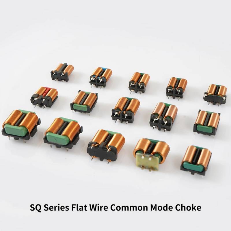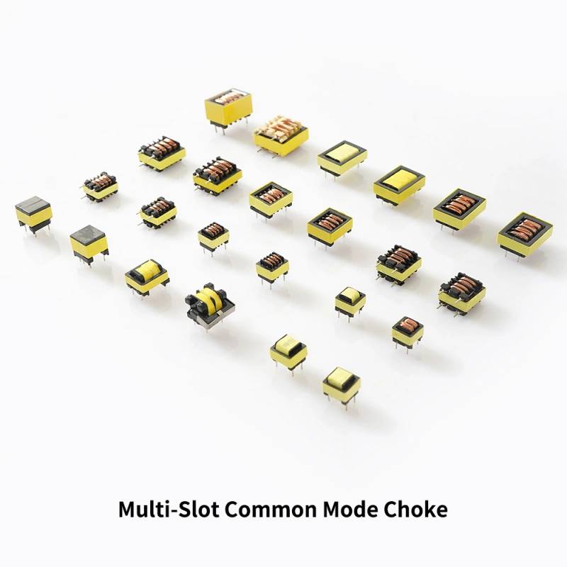
Square Common Mode Choke Overview
A Square Common Mode Choke is used to reduce unwanted noise in power and signal paths while allowing the intended current to pass through the circuit. In practical terms, it helps engineers solve EMI problems that can cause failed compliance tests, unstable communication, audible interference, or erratic behavior in switching electronics. The square-core, dual-winding structure seen in this type of component is well suited for compact assemblies where magnetic performance and board-friendly mounting matter.
Based on the visible construction, this part appears to be a wound magnetic component with two side-by-side copper wire coils on a rectangular magnetic core. That layout is commonly associated with filtering, energy transfer, and noise suppression functions in power supplies, DC-DC converters, and other electronic modules. Exact electrical ratings cannot be inferred from appearance alone, so any final selection should be based on the circuit’s required inductance, current, frequency range, and packaging constraints.
Product Structure and What It Does
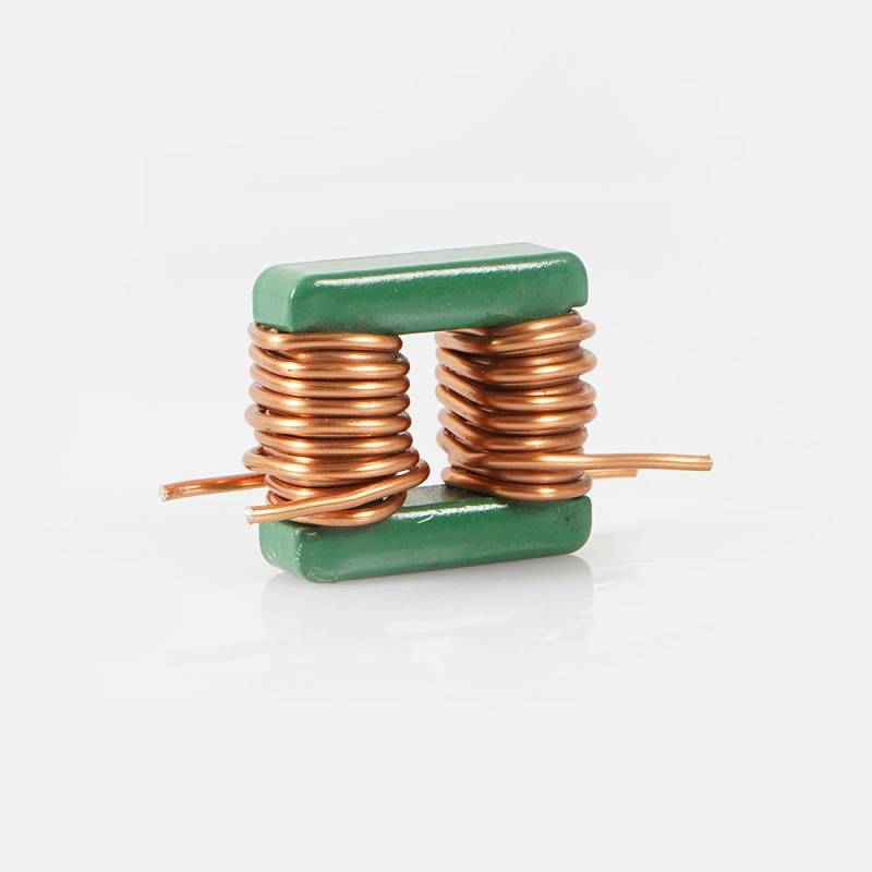
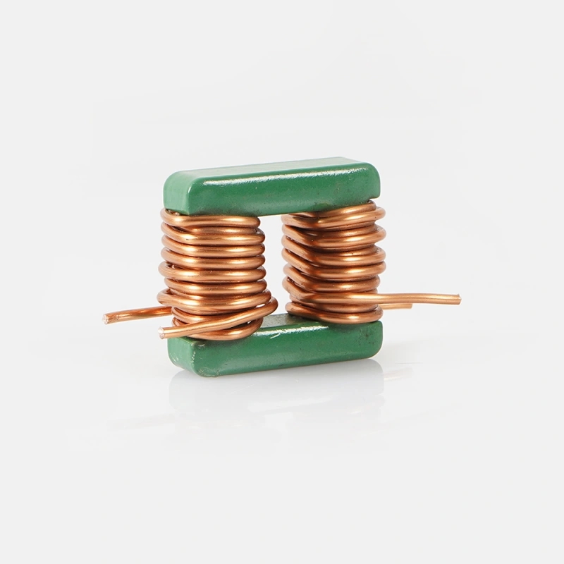
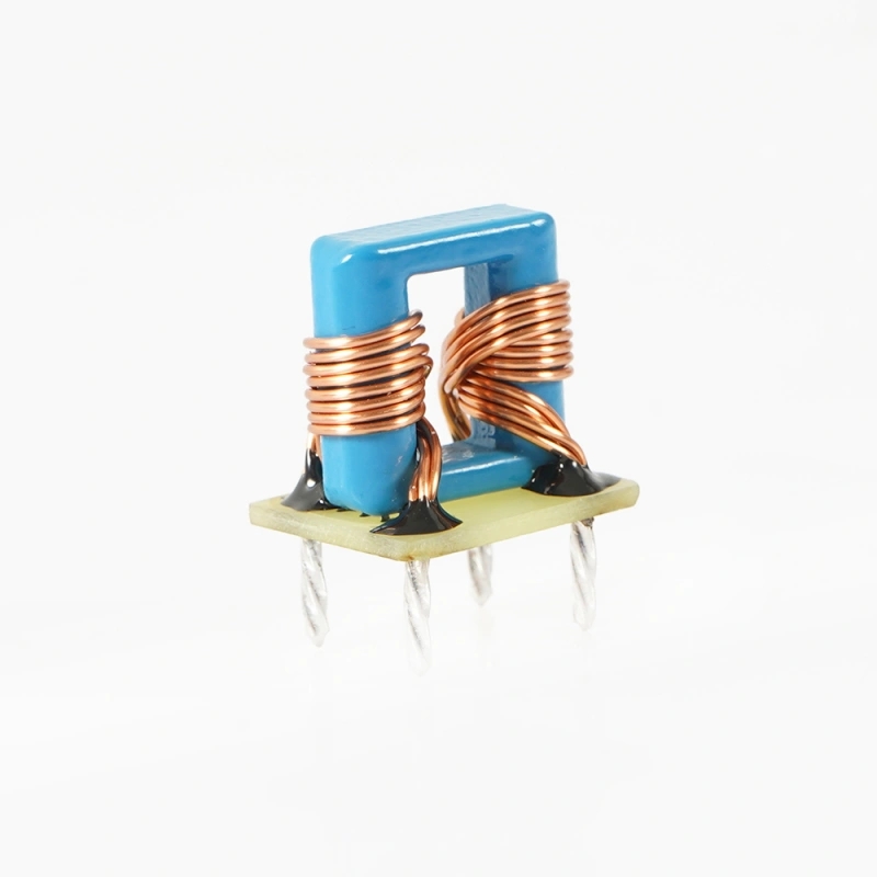
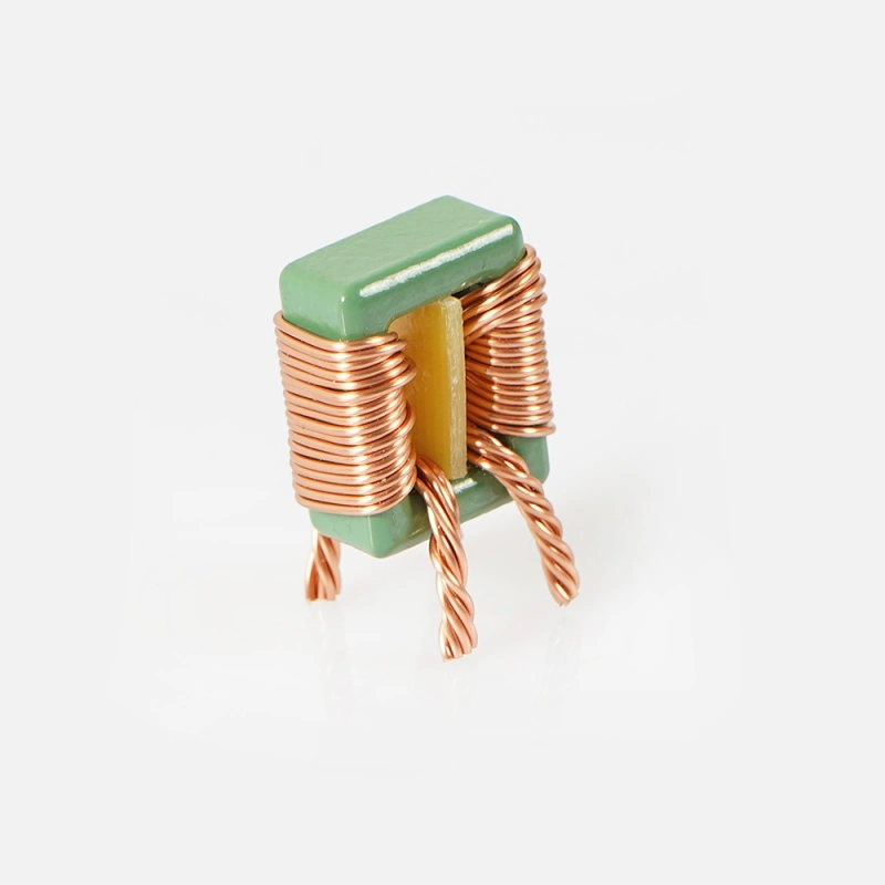
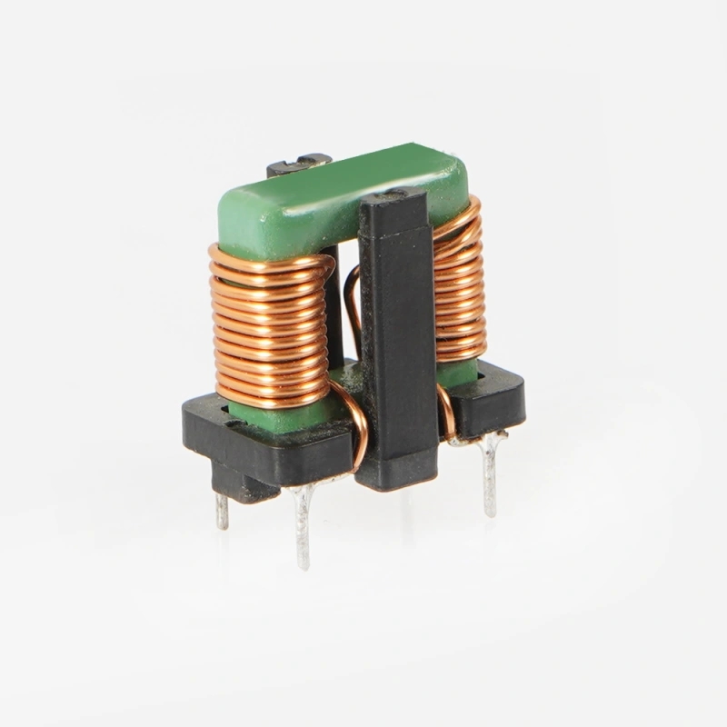
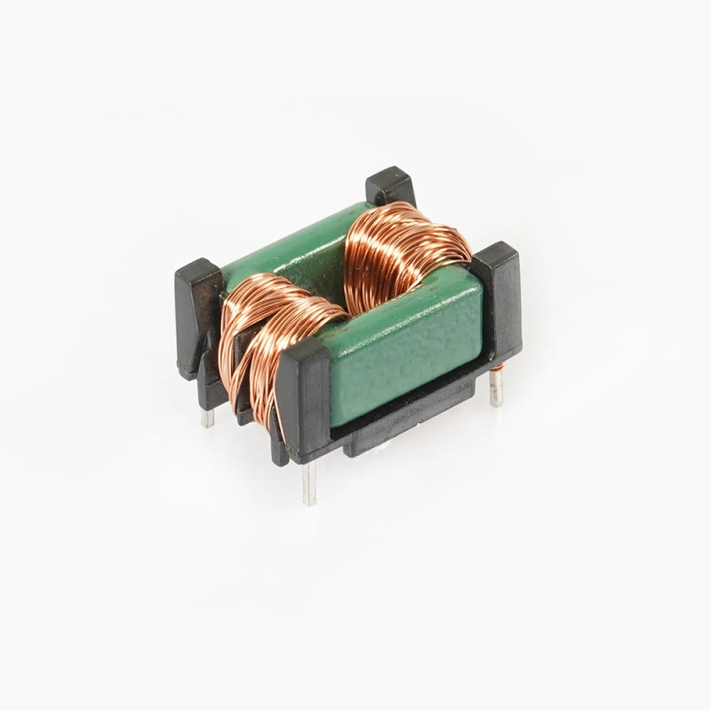
The visible part features a compact rectangular body, green outer core coating, and exposed wire leads extending from the winding ends. The copper-colored enamel wire is arranged as two closely matched coils, which is a typical geometry in magnetic components designed to handle balanced current paths or coupled magnetic flux. This geometry can be used in common-mode filtering, signal coupling, or other inductive tasks depending on the internal connection and winding orientation.
For buyers, the main value of this construction is functional control of electrical noise and magnetic behavior in a limited footprint. When circuits switch at higher frequencies, stray emissions and conducted interference often become design problems. A properly selected choke or inductor helps manage that energy so the system remains stable and easier to certify.
Visible Specifications and Construction Clues
Core Geometry
The component has a square or rectangular magnetic core form. This shape is often preferred when a compact, stackable profile is needed for PCB or wire harness integration. The top and bottom core sections appear to clamp around the windings, which is consistent with a wound magnetic assembly.
Winding Configuration
Two windings are visible, placed side by side. The exact turn count is not known, but the winding density suggests a relatively high number of turns compared with a simple power lead-through component. The wires appear enamel-coated, which is standard for magnet wire used in inductors, transformers, and chokes.
Lead Termination
The lead ends are stripped and extend outward for soldering or wiring attachment. That indicates a through-hole or lead-wire style connection rather than a surface-mount package. This format is often selected when mechanical retention, easy assembly, or custom wiring integration is required.
Likely Capabilities in Electronic Circuits
Because the exact internal design is not provided, this component should be treated as a wound magnetic device rather than a fixed labeled function. In general, parts of this type may support one or more of the following roles:
EMI suppression in switching power supplies
Noise filtering in input/output lines
Inductive energy storage in converter stages
Magnetic coupling between windings
Signal conditioning in electronics that require controlled impedance
The actual performance depends on core material, gap structure, winding orientation, insulation system, and the intended circuit topology. Those details determine whether the component behaves more like a choke, inductor, or transformer.
Materials and Finish Options
From the visible image, the wire appears to be enamel-coated copper, which is common because of its good conductivity and winding capability. The core appears to be a ferrite or ferrite-like magnetic composite, finished in a green coating or paint. That outer finish may serve protective and identification purposes, but its exact composition is not confirmed.
In custom magnetic components, material choices often affect efficiency, thermal behavior, and frequency response. Typical options may include different ferrite grades, composite magnetic materials, insulation systems, and winding wire gauges. Finish options may also vary depending on assembly requirements, such as protective coating, tape wrapping, or lead-form adjustments. Any actual option list must be confirmed by the manufacturer.
Manufacturing Process for a Wound Magnetic Component
A part like this is generally produced through a controlled winding and assembly process. Magnet wire is wound onto a bobbin or directly onto the magnetic structure, then the core halves are positioned around the windings. Leads are prepared for soldering or fixture integration, and the assembly may be secured with tape, varnish, adhesive, or a clamp-style core retainer depending on the design.
For custom production, the process usually includes material selection, winding parameter setup, lead forming, core mating, and electrical testing. In some builds, impregnation or coating is used to improve mechanical stability and reduce audible vibration. Final handling is important because lead integrity and winding alignment can affect both performance and reliability.
Typical Application Scenarios
Wound magnetic components with this visual structure are commonly used in electronics where power conversion and interference control are important. Typical scenarios include:
Switch-mode power supplies
DC-DC converter modules
Industrial control electronics
Telecom and networking hardware
Consumer power adapters
LED drivers and lighting systems
Measurement and instrumentation equipment
In these environments, the component may help reduce ripple, suppress common-mode noise, or support energy transfer between stages. The exact application depends on the circuit schematic and the magnetic design targets.
Quality Control Considerations
For buyers sourcing a Square Common Mode Choke or similar magnetic assembly, quality control should focus on measurable electrical and mechanical properties. Important checkpoints often include winding continuity, lead pull strength, insulation integrity, dimensional consistency, and inductive performance at the intended operating frequency.
Since exact ratings are not visible, it is especially important to request the datasheet or test criteria before purchasing. Relevant verification items may include inductance, DC resistance, leakage behavior, temperature rise under load, and dielectric withstand if the part is used in isolation-critical circuits. If the component is intended for EMI filtering, performance should also be validated in the final layout because PCB trace routing can significantly affect results.
Customization Guidance for Buyers
If your design needs a custom magnetic part, define the electrical target first. The most useful starting points are operating frequency, current level, allowable temperature rise, required inductance range, and the available package size. Without these inputs, a choke may be physically compatible but electrically unsuitable.
Customization can also involve lead length, mounting style, winding count, core material, and coating method. For high-volume production, repeatability is critical, so ask about process control, sample approval, and lot consistency. If the part is replacing an existing component, provide a sample, schematic reference, or measured parameters to reduce engineering iteration.
How to Evaluate This Component for Your Design
When comparing this type of part, buyers should look beyond the outer shape. The right choice depends on how the magnetic assembly behaves in the real circuit. Consider the following:
Does the circuit need EMI suppression or energy storage?
What current will flow continuously and during transients?
Is the operating frequency in the low-kHz, high-kHz, or MHz range?
Will the component be mounted on a PCB, bracket, or harness?
Are thermal limits, creepage distance, or vibration resistance important?
These questions help avoid mismatches between apparent form factor and actual electrical function. A square-core wound component may look simple, but its suitability depends on details that only test data or engineering documentation can confirm.
Why This Form Factor Is Useful
The square rectangular body is practical for compact assemblies because it can be placed efficiently in a chassis or on a board. The dual-winding layout also supports magnetic coupling in a straightforward physical package. For procurement teams, this means a component family that can often be adapted to different electrical roles without changing the basic mechanical envelope.
That flexibility is one reason wound magnetic components remain common in power electronics. They offer a balance of manufacturability, performance, and cost structure, especially when the design requires a custom magnetic profile rather than a standard off-the-shelf chip component.
Request the Right Build for Your Circuit
If you are sourcing a Square Common Mode Choke or a similar wound magnetic assembly, start with the application requirements rather than the outer appearance alone. Share your schematic, target inductance, current range, size constraints, and mounting method so the component can be matched to the circuit properly. For custom or replacement parts, clear technical information leads to better sampling and fewer redesign cycles.
Send your specifications, and the component can be evaluated for fit, function, and manufacturability based on the actual electrical need.