Square Common Mode Choke-F13X14X7 Overview
The Square Common Mode Choke-F13X14X7 is a compact PCB-mounted magnetic component used to reduce unwanted electrical noise and help circuits maintain stable operation. In power and signal paths, high-frequency interference can create errors, overheating, EMC failures, or unstable communication. This type of wound magnetic part is typically selected when a designer needs a practical way to suppress EMI/RFI at the board level without adding a large footprint or complex external filtering network.
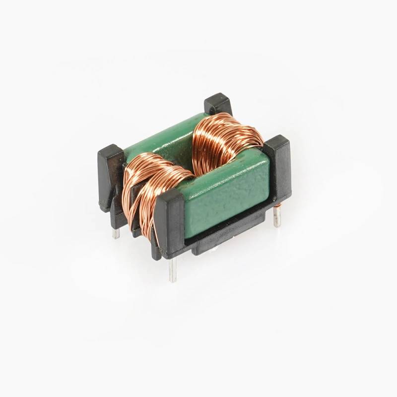
From the visible structure, this component has copper-colored enameled windings, a green ferrite or similar magnetic core, black support frames, and through-hole metal leads for soldering into a printed circuit board. The exact electrical parameters are not shown, so the page should be used as a mechanical and functional reference rather than a final specification sheet.
What This Component Does
A common mode choke or similar wound magnetic filter is used to block unwanted noise while allowing the intended current or signal to pass through a circuit. In practical terms, it helps designers address interference that can travel along power lines, data lines, or control connections. This is especially useful in compact electronics where traces are short, switching speeds are high, and interference can spread quickly across the PCB.
Because the visible product is a small wound magnetic component, it may serve as a common-mode choke, EMI filter choke, or another inductive filtering function. The exact circuit role cannot be confirmed from the image alone, so buyers should verify the electrical data before final design use.
Visible Construction and Form Factor
Rectangular compact body
The component has a square or rectangular block shape with a neat, symmetrical layout. This form factor makes it easier to place on a PCB and helps support automated or manual through-hole assembly.
Wound copper wire and magnetic core
Two visible coil sections are wrapped with fine enameled wire around a central magnetic core. The core appears green in the image, which may indicate ferrite or another molded magnetic material, but the exact material is not confirmed. The winding arrangement suggests a magnetically active part intended for filtering or energy transfer.
Through-hole lead style
The metal pins extend downward for insertion into PCB holes. Through-hole mounting is often preferred for components that need mechanical retention, stable solder joints, and reliable assembly in power electronics or industrial boards.
Key Specifications and Capabilities to Confirm
Several critical specifications are not visible and should be checked on the engineering drawing, test sheet, or supplier documentation before purchase:
- Inductance value
- Current rating
- DC resistance
- Voltage rating
- Operating temperature range
- Pin spacing and exact dimensions
- Common-mode attenuation performance
- Insulation and safety requirements for the target application
For buyers evaluating this part as a Square Common Mode Choke-F13X14X7, the most important point is matching the component to the circuit’s noise profile and electrical load. A choke that is too small may saturate or fail to reduce interference effectively. One that is oversized may increase cost or occupy more board space than necessary.
Materials and Finish Options
Based on visible features, the part uses copper-colored enameled wire, a magnetic core, and dark molded supports or bobbin-style end frames. These are standard material choices for wound magnetic components because they offer a balance of conductivity, magnetic performance, insulation, and mechanical stability.
Possible finish and material options, depending on the supplier’s build, may include different wire gauges, lead plating styles, core compositions, and molding or epoxy materials. However, exact variants should not be assumed unless they are listed in the procurement data or confirmed by sample inspection.
Manufacturing Process for Wound Magnetic Components
The visible structure indicates a typical magnetic-component manufacturing flow. First, the wire is wound around the core or bobbin assembly with controlled turn count and tension. Next, the leads are formed and secured, and the windings are positioned within the frame structure. After assembly, the part may go through electrical testing, visual inspection, and final packaging for PCB use.
In products like the Square Common Mode Choke-F13X14X7, process control matters because winding consistency directly affects inductance, resistance, and noise-filtering behavior. Alignment of the core and lead pins also influences assembly reliability and long-term mechanical stability.
Typical Application Scenarios
This kind of choke is commonly used wherever electrical noise must be managed at the board level. Typical use cases include:
- Switching power supplies and DC-DC converters
- Industrial control boards
- Consumer electronics with compact PCB layouts
- Telecom equipment and communication modules
- Automotive electronics where EMI control is important
- Signal conditioning and line filtering circuits
In these systems, the goal is to improve signal integrity, reduce conducted emissions, and help the product pass electromagnetic compatibility requirements. The exact placement depends on the circuit topology and the type of interference being managed.
Quality Control and Inspection Considerations
For wound magnetic parts, quality control usually centers on mechanical consistency and electrical repeatability. Buyers should ask for verification of turn count, lead alignment, winding integrity, core assembly, and solderability. If the part is intended for production use, incoming inspection should also check dimensions, pin pitch, and visible defects such as wire damage or frame cracking.
Electrical testing is especially important when the component is used in filtering applications. Even if two parts look identical, differences in winding or core characteristics can change performance. For this reason, sample validation on the target PCB is more useful than relying on appearance alone.
Customization Guidance for Buyers
If this component is being sourced for a new design, customization may be needed to match the electrical and mechanical requirements of the board. Buyers often request adjustments in winding count, lead form, pin spacing, body size, core material, or insulation structure. Some projects may also need tighter dimensional matching for automated insertion or enclosure clearance.
When requesting a custom or semi-custom version of the Square Common Mode Choke-F13X14X7, provide the following information whenever possible:
- Target application and circuit role
- Required inductance or attenuation range
- Operating current and thermal limits
- Board layout drawings or pin spacing needs
- Environmental conditions such as vibration, humidity, or temperature stress
- Required qualification or compliance targets
This information helps the manufacturer recommend a more suitable winding and core configuration without unnecessary trial-and-error.
Buyer Decision Factors
When comparing similar PCB magnetic components, buyers usually evaluate more than just the outer size. The main decision factors include electrical performance, package compatibility, assembly method, and long-term reliability. For this type of part, it is wise to confirm whether the design is truly a common mode choke, a transformer, or another inductive element, since the internal structure can affect circuit behavior.
Other practical considerations include whether the part fits the available footprint, whether the leads match existing PCB tooling, and whether the component can maintain performance under the expected frequency and load conditions. If the design will be used in a noise-sensitive product, prototype testing is strongly recommended.
Why This Form Factor Is Useful in PCB Design
The square through-hole layout combines compact size with easier handling during assembly. Compared with larger external filters, a board-mounted choke can reduce parts count and keep the filter path close to the noise source. That usually improves layout efficiency and can make EMC tuning more straightforward during product development.
The visible dual-winding structure also suggests a design intended for controlled magnetic behavior rather than simple wire connection. That makes it a practical choice for electronics teams seeking a stable, repeatable filtering element in a compact package.
Requesting the Right Version
Since the image does not show exact inductance, current rating, or pin pattern, buyers should not assume interchangeability with another square choke of similar appearance. A close visual match can still differ significantly in electrical performance. The safest approach is to compare the target board requirements with supplier data before approving samples or placing volume orders.
If you are sourcing the Square Common Mode Choke-F13X14X7 for a power or signal board, prepare your schematic notes, footprint drawing, and performance targets before inquiry. This will help narrow the correct configuration and reduce revision cycles.
Inquiry and Technical Support
For purchasing, customization, or part-matching questions, send the circuit requirements, board layout, and any existing sample details to the supplier. Clear technical input makes it easier to identify the right wound magnetic component for EMI suppression, filtering, or related PCB applications.
If you need a compact through-hole magnetic filter for an electronics project, the Square Common Mode Choke-F13X14X7 is a useful starting point for design review and sourcing discussion.