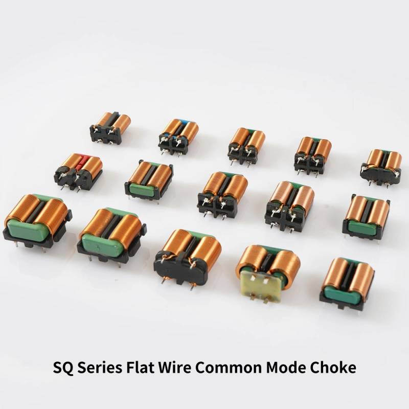
SQ Flat Wire Common Mode Choke Overview
The SQ Flat Wire Common Mode Choke is used to reduce unwanted common-mode noise in power and signal circuits, helping equipment pass cleaner power and operate more reliably. For buyers designing power supplies, converters, or industrial control boards, the main problem is often electromagnetic interference that causes instability, failed compliance tests, audible noise, or poor system performance. A properly selected common mode choke addresses that issue by suppressing noise while keeping the useful current path intact.
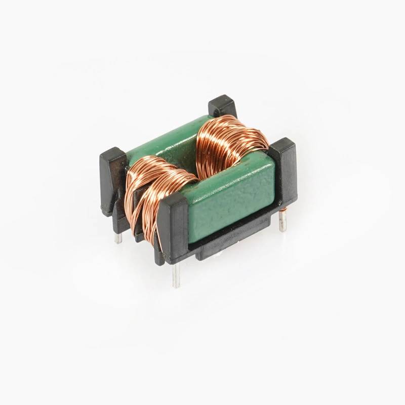
From the visible construction, this component appears to be a compact electromagnetic coil assembly with dual windings, a central magnetic core or bobbin structure, a molded support frame, and through-hole terminals for PCB mounting. The flat wire construction is often chosen in applications that need efficient winding use and a compact footprint, although the exact electrical ratings are not visible and should be confirmed from the actual specification sheet.
Product Structure and Working Principle
A common-mode choke is designed to present high impedance to noise currents that travel in the same direction on multiple lines, while allowing the intended differential current to pass with less disturbance. In practical terms, it helps filter high-frequency interference generated by switching circuits, cable coupling, or external electromagnetic sources.
This unit appears to use two symmetrical copper windings arranged around a shared magnetic structure. That layout is typical for common-mode suppression because it creates magnetic cancellation for normal operating current and stronger impedance for unwanted noise. The visible black molded frame supports the coil geometry and helps secure the terminals for board assembly.
Key Visible Features
Compact open-frame construction
The component has a rectangular, open-frame form factor that is easy to place on a printed circuit board and can suit space-conscious designs.
Dual winding layout
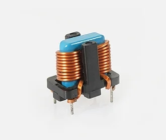
Two balanced windings are visible on either side of the center section. This symmetry is important for common-mode filtering performance.
Through-hole terminals
Metal pins extend downward for PCB insertion and soldering, which is useful for robust mechanical retention in industrial and power electronics assemblies.
Insulated top section
A blue insulating tape or sleeve is visible near the top, likely serving as part of the coil insulation and mechanical protection. Exact insulation details are not identifiable from the image alone.
Specifications and Capabilities to Confirm
Because the visible image does not show a datasheet, several important electrical and mechanical parameters should be confirmed before purchase or integration.
- Inductance value
- Rated current
- DC resistance
- Operating frequency range
- Insulation system
- Core material
- Dimensions and pin pitch
- Temperature performance
For engineering use, these values determine whether the choke will work in the target circuit without overheating, excessive voltage drop, or reduced filtering efficiency. The right selection depends on the noise spectrum, current level, board space, and thermal conditions of the end product.
Materials and Finish Options
Based on the visible product, the assembly includes copper windings, a likely magnetic core or bobbin center section, a black molded support body, and metallic leads. These material choices are common in coil assemblies because they balance electrical conductivity, magnetic performance, and mechanical stability.
Possible finish options in similar products may include tinned leads for solderability, different coil insulation materials, and various core or bobbin materials depending on the required temperature and electrical characteristics. Since the exact build is not specified here, material selection should be matched to the application rather than assumed.
Manufacturing Process
The likely manufacturing flow for an SQ Flat Wire Common Mode Choke starts with winding copper wire around the magnetic core or bobbin. Flat wire or formed wire may be used to improve packing density and fit within the compact geometry. After winding, the assembly is positioned into the molded support frame, and the terminals are formed to suit through-hole PCB mounting.
Insulation tape or sleeve material is then applied where needed to maintain dielectric separation and stabilize the coil structure. Final steps usually include visual inspection, electrical testing, and packaging for assembly use. Depending on design requirements, manufacturers may also control lead forming, solderability, and dimensional consistency during production.
Typical Application Scenarios
This type of common mode choke is often used in circuits where electromagnetic noise needs to be controlled without adding a large part footprint. Common use cases include:
- Switch-mode power supplies
- DC-DC converter input or output filtering
- Inverter and motor drive circuits
- Industrial control electronics
- Consumer power adapters and charging equipment
- General EMI/RFI suppression stages
In these systems, the choke can help reduce conducted emissions, improve system stability, and protect nearby components from high-frequency interference. It is especially relevant in designs where cable length, switching speed, or dense layouts increase noise sensitivity.
Quality Control Considerations
For a component like this, quality control should focus on consistency and electrical integrity. Buyers usually want assurance that the windings are properly aligned, the insulation is intact, and the terminals are firmly seated for soldering.
Useful inspection and test points include visual checks for winding damage, pin alignment, secure molding, and contamination. Electrical verification generally looks at inductance, resistance, and dielectric integrity according to the product’s intended rating. If the choke will be used in a safety-related or compliance-driven product, consistency between lots becomes especially important.
Customization Guidance for OEM Buyers
When sourcing an SQ Flat Wire Common Mode Choke for an OEM design, the most important customization questions usually involve electrical performance, mounting geometry, and thermal behavior. Buyers should define the expected operating current, noise frequency range, board footprint, and any space limitations early in the design process.
Depending on the supplier’s capability, customization may involve adjusting the winding turns, wire form, terminal spacing, core selection, insulation structure, or package size. For compact power electronics, small changes in winding geometry can affect both filtering behavior and thermal loss, so sample verification is advisable before committing to volume production.
How to Evaluate the Right Choke for Your Project
Not every common-mode choke is interchangeable. A buyer should compare more than just size. The key decision factors usually include noise suppression target, current handling, temperature rise, mounting method, available PCB area, and compliance requirements.
If the design uses high switching frequency, fast edges, or long external cables, stronger filtering may be required. If the current is high, a low-resistance design and suitable thermal margin become more important. For automated PCB assembly, lead form and dimensional repeatability can also matter as much as the electrical values.
Because the visible product appears to be a through-hole magnetic component with a compact footprint, it may be well suited to applications where mechanical retention and moderate power handling are priorities. Final suitability should still be confirmed against the electrical specification.
Why This Component Form Is Practical
The visible coil arrangement offers a straightforward balance of structure and function. The dual-winding architecture is appropriate for suppressing common-mode noise, while the molded frame and leaded mounting style simplify integration into traditional PCB workflows. For many power and industrial applications, that combination is easier to handle than a purely surface-mount approach, especially where mechanical durability is important.
Because the image does not reveal hidden performance data, this page should be treated as a product reference for form, likely function, and integration considerations rather than a final electrical datasheet.
Request Support for Your Design
If you are evaluating the SQ Flat Wire Common Mode Choke for a power supply, converter, inverter, or EMI suppression circuit, prepare your target current, board space, operating frequency, and preferred mounting style before requesting a quote or sample. Clear requirements make it easier to match the correct winding structure and verify fit early in the development process.
Share your circuit needs, and the component can be checked against the application instead of relying on appearance alone. That approach reduces redesign risk and helps ensure the choke performs as intended in the final assembly.