Overview of the PQ2620 Flyback Transformer
Switch-mode power supplies frequently struggle to balance core volume, thermal dissipation, and physical PCB real estate. The PQ2620 flyback transformer addresses this engineering trade-off by utilizing the standardized Power Quadrilateral (PQ) core profile, which maximizes winding window area relative to the ferrite cross-section. Designed as an isolated magnetic component for energy storage and voltage translation, this geometry delivers reliable magnetic shielding and lower winding resistance compared to older, bulky E-core designs. In flyback configurations, the assembly handles peak energy storage during the primary on-phase and releases energy across single or multiple outputs during the off-phase, minimizing overall circuit footprint in switched-mode systems.
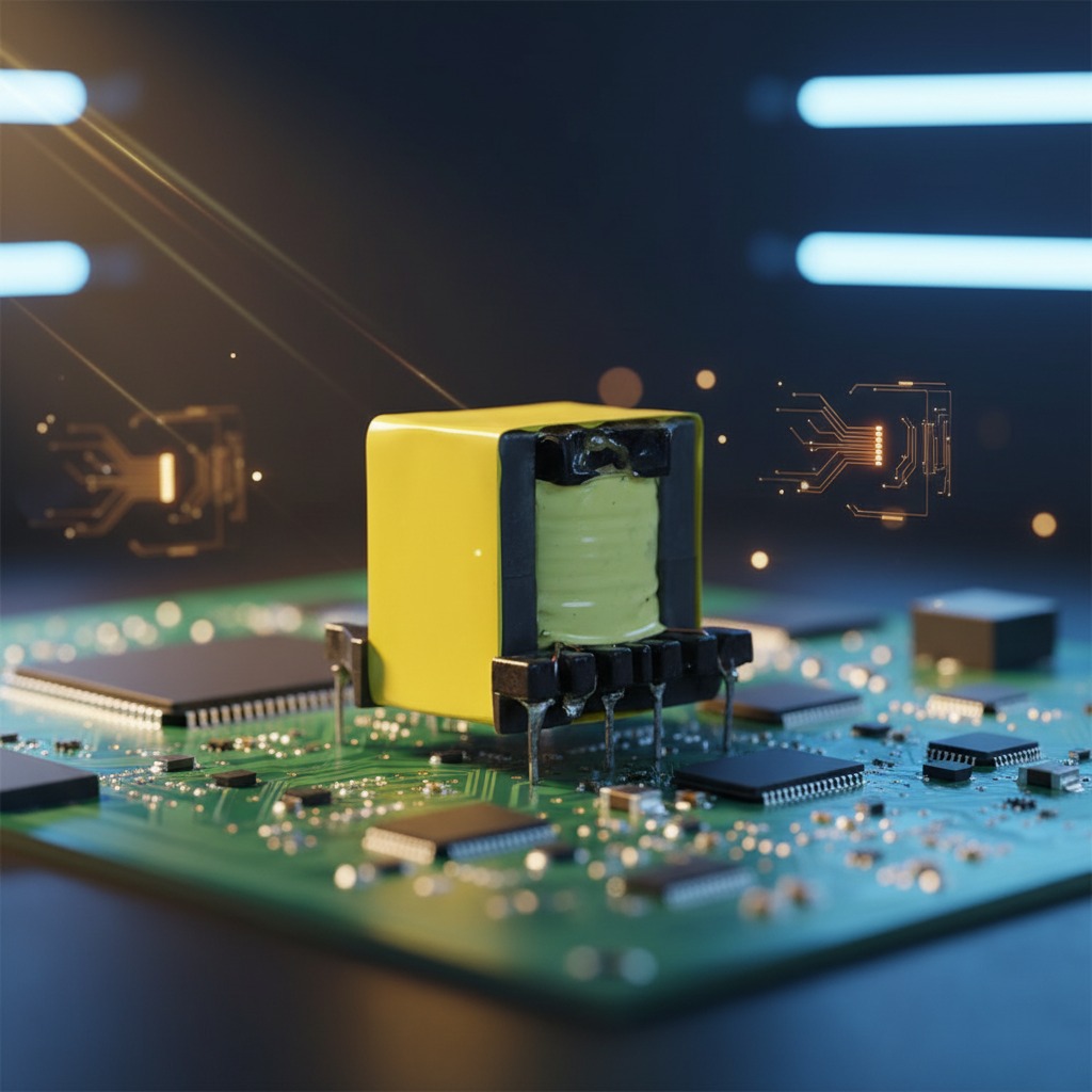
Core Architecture and Mechanical Specifications
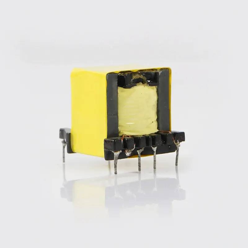
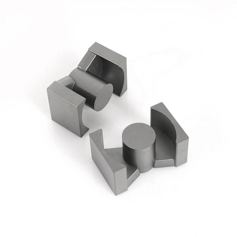
The PQ26/20 transformer standard combines a nominal 26 mm outer core diameter with an approximate 20 mm stack height. The round center post surrounded by a round-to-square magnetic circuit provides two distinct mechanical advantages: it reduces the mean length per turn (MLT) of copper wire to keep copper losses low, and it offers superior self-shielding against radiated electromagnetic interference (EMI).
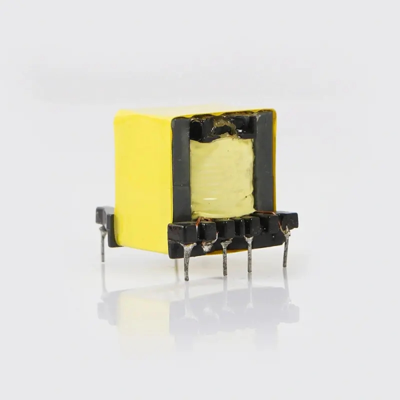
This design utilizes a vertical 6+6 pin transformer bobbin yielding 12 discrete through-hole (THT) terminal pins. The vertical orientation allows power supply engineers to minimize board surface area on dense PCBs where vertical clearance permits. Straight tinned wire pins exit cleanly from the plastic carrier base, allowing straightforward lead routing, robust solder fillet formation, and unobstructed visual inspection on automated surface-mount and mixed-technology assembly lines.
Materials and Structural Execution
Magnetic components in this class depend directly on thermal endurance and dielectric reliability:
- Magnetic Core: Constructed using a matched pair of low loss ferrite core transformer halves. Because energy storage in a high frequency flyback transformer primarily resides within the magnetic path's air gap, core sets for flyback operation are ground to a designated gap length or AL value to prevent saturation under peak magnetization currents.
- Bobbin Base: Molded from rigid, high-temperature engineering thermoplastic (or phenolic material) with distinct barrier walls to separate the primary and secondary pinouts while maintaining requisite pin pitch.
- Conductors: High-grade enameled copper magnet wire, custom-layered to balance skin effect and proximity losses at target switching speeds.
- Insulation and Outer Layer: Multi-layer yellow polyester/mylar electrical tape provides mechanical containment and isolation barrier integrity across the perimeter. Visible units also feature clear varnish impregnation to immobilize loose turns, dampen acoustic noise caused by magnetostriction, and protect against humidity.
Manufacturing Workflow
Fabrication of a custom flyback power transformer follows a tightly controlled process flow to maintain electrical tolerances:
First, programmatic CNC multi-spindle winders place the primary, secondary, and auxiliary bias windings onto the bobbin according to the engineer's turns-ratio schematic. Intermediate insulation layers and margin tapes are inserted to establish necessary creepage distances. Second, wire tails are skeletal-routed, wrapped, and terminated to the 12 base pins, followed by precision tin dipping or flux soldering.
Following winding completion, matched ferrite halves are assembled around the bobbin. If the design targets specific inductance tolerances, the core center leg is ground or shimmed to calibrate primary inductance (Lp). The core is secured via specialized clip retainers or wrapped with electrical-grade bonding tape. Assemblies routinely undergo vacuum-pressure varnish impregnation and curing ovens to ensure void-free insulation bonding throughout the internal layers.
Typical Application Environments
The PQ26/20 geometry serves broad commercial and industrial sectors, functioning as an SMPS ferrite transformer in medium-power conversion tiers (typically 50 W to 150 W depending on switching frequency, thermal dissipation, and ambient cooling). Common applications include:
- Universal-input AC-DC flyback converters, industrial power modules, and auxiliary standby supplies.
- High-density battery chargers and AC adapters where form-factor compactness is critical.
- Isolated DC-DC step-down and step-up modules for telecom, automation, and instrumentation boards.
- Constant-current and constant-voltage LED drivers requiring reinforced insulation barriers.
Engineering Parameters for Custom Specification
Because the visible physical sample represents a hardware shell rather than an off-the-shelf universal component, buyers developing a custom flyback power transformer should specify internal electrical parameters during quoting:
- Primary Inductance and Tolerance: Target Lp (typically specified in microhenries at 10 kHz or 100 kHz) and allowable inductance tolerance (e.g., ±10%).
- Leakage Inductance Threshold: Maximum permissible primary leakage inductance (Lkp) measured with secondary terminals shorted, essential for snubber network sizing and switch stress reduction.
- Operating Frequency: Optimized winding patterns vary whether configured for 65 kHz, 100 kHz, or as a 140kHz flyback transformer where Litz wire or sandwiched interleaving may be necessary to combat eddy-current losses.
- Isolation Voltage / Hi-Pot: Dielectric withstand specifications (e.g., primary-to-secondary dielectric rating, such as 3.0 kVAC to 4.0 kVAC for 60 seconds).
- Winding Pinout Matrix: Output voltage rails, auxiliary supply taps, and pin assignment layout for the vertical 6+6 pin transformer format.
Quality Control and Testing Standards
Reliable production runs require continuous batch verification before packaging. Standard production testing encompasses 100% checks of primary inductance and leakage inductance using precision LCR meters. High-potential (Hi-Pot) dielectric testing verifies insulation barriers between primary, secondary, and core grounds to verify zero flashover or excessive leakage current. Finished parts are also inspected for dimensional pin coplanarity, solderability, and resistance to soldering heat to guarantee seamless automated insertion into through-hole PCB production lines.
Specification Inquiries and Custom Prototypes
Whether you require a standard replacement bobbin build or an application-tailored winding design, engineering teams can configure this platform to match exact switching thresholds, regulatory creepage distances, and multiple output rails. Contact our technical team with your target switching topology, input/output schematics, and mechanical height constraints to initiate sample winding and characterization tests.