FeSi FeSiAl Toroidal Inductor Overview
The FeSi FeSiAl Toroidal Inductor is used when a circuit needs compact magnetic performance for filtering, energy storage, or noise suppression. In many electronics assemblies, the buyer problem is not simply “adding a coil,” but controlling ripple current, reducing EMI, and fitting a magnetic component into a limited PCB area. This toroidal, through-hole part addresses that need with a wound circular core structure and pin-style mounting that is practical for power supplies, DC-DC converters, and board-level prototyping.
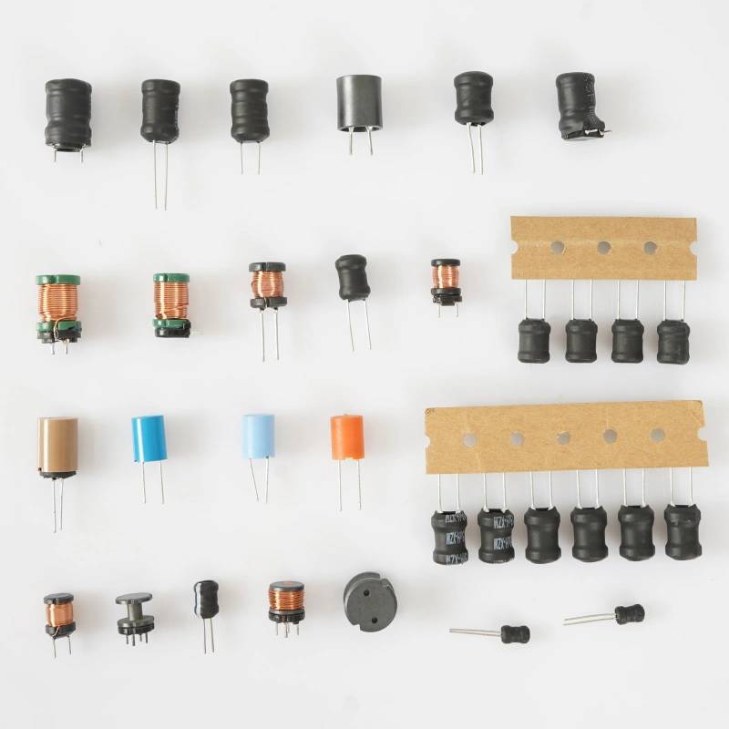
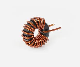
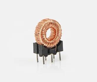
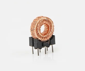
From the visible construction, this component appears to be a small toroidal magnetic device with copper-colored winding around a ring-shaped core and a black molded base with multiple through-hole pins. The exact core material, inductance, and current rating are not visible, so those values should be confirmed before design-in. Even so, the format itself gives several useful advantages: a compact footprint, secure PCB mounting, and a shape that is commonly chosen for stable magnetic behavior in filtering and power conversion tasks.
Product Structure and What It Means for Buyers
A toroidal inductor is built around a ring-shaped core, with wire wound evenly around the circular path. This geometry is widely used because it can help concentrate magnetic flux inside the core and reduce stray field radiation compared with some open magnetic structures. In practical terms, that can support cleaner operation in nearby circuitry, especially where electromagnetic interference matters.
The visible part shows a wound copper coil mounted on a compact base with through-hole leads. That style is often preferred in assemblies that need firm mechanical retention on the PCB. It also supports manual soldering, wave soldering, or other board-level assembly methods depending on the end product’s process flow. Because the exact material system is not disclosed, the part should be treated as a toroidal magnetic component suitable for electrical and mechanical integration, rather than assumed to have any specific ferrite or powdered-iron behavior.
Key Capabilities and Typical Functions
Filtering and noise suppression
This type of component is commonly used in EMI/RFI filtering paths. In power electronics, it may help reduce high-frequency switching noise and smooth current ripple. In signal-conditioning or auxiliary circuits, it can contribute to suppressing unwanted interference before it reaches sensitive sections of the board.
Energy storage in power conversion
Inductors store energy in a magnetic field during current flow and release it when the circuit requires it. That behavior is central to DC-DC converters, switching regulators, and other power stages. A toroidal form factor is often selected where efficient magnetic containment and compact layout are important.
General circuit prototyping and replacement
Because the component uses through-hole pins, it is also practical for prototyping, service replacement, and small-batch assembly. Engineers can test a design on a PCB with a leaded magnetic component before moving to a final layout or custom-wound part.
Visible Specifications and What Should Be Confirmed
Only the following facts are visible from the provided image description:
- Torodial wound magnetic construction
- Copper-colored wire winding
- Black molded or plastic support/base
- Multiple through-hole pins for PCB mounting
- Compact upright footprint
Items that are not visible and should not be assumed include inductance value, DC resistance, current capacity, saturation behavior, operating frequency range, exact pin count, dimensions, temperature class, and core composition. For engineering procurement, those details are critical. If the part will be used in a production design, request a datasheet or a measured sample before release.
Materials and Finish Options
Based on the image, the winding appears to be copper or copper-finished magnet wire. The support base looks like a black molded insulating body or plastic carrier. The metal pins are designed for through-hole connection. These material choices are common in leaded magnetic assemblies because they support solderability, stability, and straightforward PCB integration.
For toroidal inductors in general, finish and material options may vary by application. Copper winding gauge can be selected to suit current demands, while insulation type and winding arrangement may be adapted for thermal or voltage requirements. If the component is custom-made, buyers often specify lead length, pin pitch, base material, and winding termination style. Because none of those custom details are supplied here, they should be treated as options to discuss rather than standard features.
Manufacturing Process
The basic manufacturing flow for a part of this type typically includes core preparation, wire winding, lead attachment or pin assembly, insulation checks, and final mounting into the base structure. The toroidal winding step is especially important because winding tension, turn count, and termination quality all influence repeatability. After assembly, the component is usually inspected for mechanical stability and solderable pin condition.
If the part is being sourced as a custom-wound item, the production route may also include winding verification, dimensional inspection, and electrical testing according to buyer-defined targets. Since no exact test data is provided, it is best to define the acceptance criteria early in the sourcing process.
Application Scenarios
The FeSi FeSiAl Toroidal Inductor format is relevant in a wide range of electronics where compact magnetic parts are needed:
- Switching power supplies
- DC-DC converters
- EMI and RFI suppression circuits
- Input/output filtering networks
- Signal conditioning stages
- Embedded system prototypes
- Replacement parts for board repairs
In these environments, the toroidal shape can be useful where low stray field emission is valued and where board space is limited. The through-hole format also makes the part suitable for products that are still using leaded assembly rather than surface-mount-only designs.
Quality Control Considerations
For buyers, quality control is not limited to visual appearance. A magnetic component should be checked for winding consistency, pin alignment, solderability, mechanical anchoring, and conformance to the specified electrical target. If the component is intended for a power circuit, the real concern is whether it behaves consistently under load and temperature conditions relevant to the application.
Because no certification, tolerance, or electrical test result is included in the supplied data, it would be unsafe to claim any exact performance level. Instead, buyers should verify the following before approving the part:
- Inductance at the intended test frequency
- DC resistance
- Current handling margin
- Pin spacing and PCB footprint
- Thermal behavior in the final enclosure
- Compatibility with soldering and assembly process
Customization Guidance for OEM and EMS Buyers
If you are sourcing this as a custom component rather than a standard catalog item, start with the circuit requirement. The most useful inputs are the target inductance, operating current, frequency range, size envelope, and mounting constraints. From there, the supplier can evaluate winding turns, conductor gauge, core selection, and lead arrangement.
For procurement teams, it helps to define the PCB footprint early. The visible part uses through-hole pins, so hole size, row spacing, and mechanical clearance all matter. If the application includes vibration or repeated handling, ask about base retention and lead robustness. If the circuit is sensitive to temperature rise, request thermal and electrical test data that matches your use case.
How to Choose the Right Toroidal Inductor
Several buyer decision factors usually determine whether a toroidal inductor is the right fit:
- Electrical target: inductance, resistance, and current demand
- Mechanical fit: board footprint, lead style, and height
- Noise requirements: EMI suppression and magnetic field containment
- Assembly method: manual insertion, wave soldering, or automated assembly
- Supply strategy: standard part, approved equivalent, or custom-wound design
Choosing the right part is often a balance between magnetic performance and production practicality. A compact component may fit the board, but still need validation for heat rise, tolerance, and long-term reliability. For this reason, final selection should always be tied to the circuit’s actual operating conditions.
Requesting a Quote or Technical Check
If you need a FeSi FeSiAl Toroidal Inductor for a new design, prototype build, or replacement program, share the required electrical targets and PCB constraints first. That allows the supplier to confirm whether the visible form factor is a match and whether a standard or custom winding approach is appropriate. For manufacturing projects, it is especially useful to provide the target footprint, required inductance range, and expected operating current.
Send your specification sheet, sample photo, or board drawing to start the technical review. The more clearly the application is defined, the faster the part can be matched to the circuit.