Solving High-Frequency Line Noise in Compact Power Supplies
Switch-mode power topologies and high-efficiency AC/DC converters frequently generate high-frequency electrical disturbances that couple back into utility lines or disrupt sensitive downstream components. Engineering teams facing radiated and conducted emission test failures need repeatable attenuation without sacrificing valuable board space. The F0810 common mode choke addresses this design bottleneck by providing targeted common-mode attenuation on AC mains inputs and low-voltage DC rails. Built upon the standardized UU8.5 geometry, this component acts as a high-impedance barrier against unwanted noise signals while allowing differential operating currents to pass unimpeded.
Product Overview: UU8.5 / F0810 Core Architecture
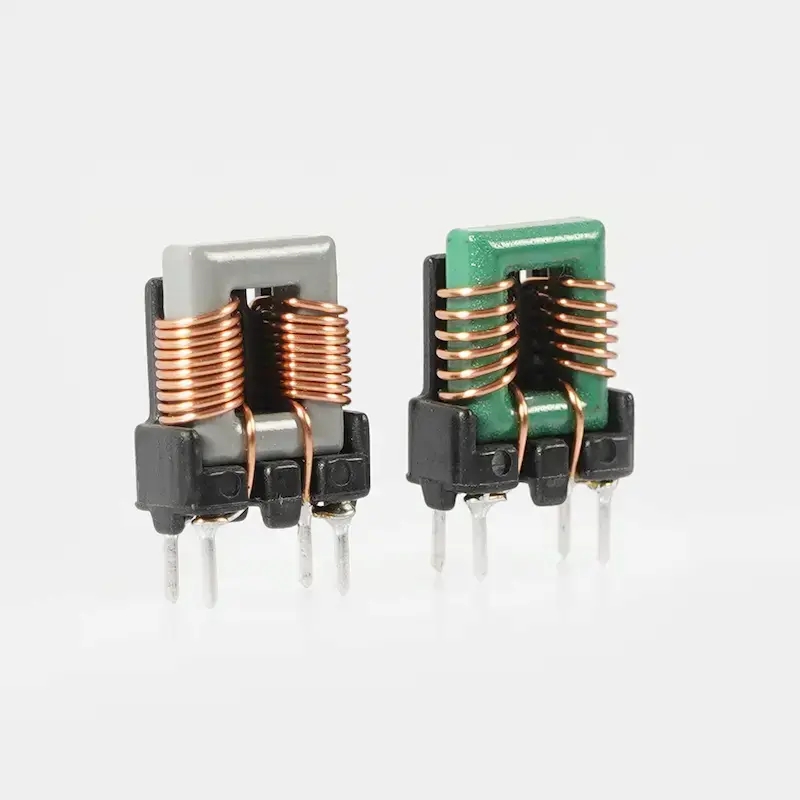
The F0810 series belongs to the UU family of closed-loop magnetic components. Each unit consists of two matched U-profile core segments that unite to form a continuous magnetic circuit across two winding legs. By positioning an independent copper winding on each leg, the component generates cancellation flux for common-mode currents while differential power currents induce opposing fluxes that balance out, preventing core saturation under standard load conditions.
As a through hole common mode inductor, the mechanical assembly is stabilized by a molded plastic header base with four vertical termination pins arranged in a symmetrical two-by-two grid. This configuration provides superior mechanical anchoring against vibration and mechanical shock compared to radial or cantilever leaded parts. While specific pin pitch and terminal diameter vary by production tooling, the four-pin through-hole layout ensures secure wave soldering and stable board integration.
Materials and Finish Variants
The construction of this ferrite common mode choke combines standard magnetics materials engineered for predictable electromagnetic performance:
- Core Material: Soft ferrite halves forming a closed magnetic path. Visual inspection indicates at least two finish options: an unpainted gray sintered ferrite core and a green-coated variant. The green finish is typically an applied paint or epoxy barrier, which may offer enhanced edge insulation or denote a specific core grade; buyers should verify the exact dielectric breakdown voltage and material grade on the component specification sheet.
- Winding Wire: Enamelled copper magnet wire wound uniformly across both legs. Wire diameter and turns count dictate the final inductance, DC resistance (DCR), and current-handling limit.
- Base Header: Black rigid thermoplastic bobbin that isolates the windings, seats the core segments, and fixes the through-hole pin terminals.
- Terminals: Four rigid vertical metal pins with a tinned surface finish to promote solder wetting during standard leaded or lead-free assembly processes.
Wound Component Manufacturing Flow
Producing a reliable common mode coil requires process consistency across each fabrication stage:
- Core Preparation: Ferrite segments are inspected for mechanical integrity and micro-cracks before assembly. For coated variants, the protective layer is applied and cured to ensure uniform thickness across corners.
- Coil Winding: Two matched windings are placed on the bobbin legs. Maintaining equal winding tension and identical turn counts on both sides is critical to prevent differential-to-common mode conversion.
- Core Assembly and Pin Termination: The core halves are seated around the wound bobbin, secured, and the copper magnet wire leads are stripped, routed, and soldered or welded to the header pins.
- Electrical Screening: Typical production inspection includes continuity verification, coil balance checks, and winding inductance measurements to ensure production uniformity across lots.
Application Scenarios
Engineers specify the UU8.5 choke coil across various low-to-medium power electronics sectors where space constraints and noise compliance intersect:
- Auxiliary and Main Switch-Mode Power Supplies (SMPS): Placed at the AC input stage to suppress line feedback and help circuits satisfy regional EMC standards.
- LED Lighting Drivers: Serves as an EMI filter inductor to damp noise generated by high-speed pulse-width modulation (PWM) switching circuits.
- Consumer Appliances and Adapters: Installed as a board-level power line noise filter in chargers, smart metering units, and small motor controllers.
- Industrial Control Boards: Isolates differential signal lines and DC distribution busses against common-mode plant noise.
Buyer Decision Factors and Customization Parameters
Because magnetic core properties depend strictly on application operating parameters, procurement and design engineers should evaluate specific electrical criteria before ordering:
- Inductance and Saturation: Inductance values (mH or µH), test frequency (typically 1 kHz to 100 kHz), and saturation thresholds are customized based on wire turns and core permeability. These values are not standard across all F0810 parts and must be clarified per drawing.
- Rated Current and Thermal Rise: Operating current capacity is limited by the gauge of the enameled copper wire and the allowable temperature rise of the assembly.
- Mechanical Clearances: Overall component height, lead length, and PCB footprint grid dimensions must be confirmed against your mechanical enclosure limits.
- Core Coating Function: Clarify whether the green-coated variant is required for elevated environmental resistance, insulation compliance, or core permeability identification.
Specification and Sourcing Inquiries
Whether you are designing a new power supply filter stage or securing an alternate source for existing UU8.5 choke coil footprints, our engineering team can review your functional requirements. Submit your required inductance target, operating current, pin pitch dimensions, and schematic configuration to receive technical datasheets and sample availability.