Product Overview: EE8.3 Common Mode Choke
Designing compact power conversion circuitry requires careful balancing of electromagnetic compatibility and board real estate. The EE8.3 common mode choke addresses this design challenge by filtering high-frequency electrical noise out of input and output stages without requiring excessive PCB surface area. Built on a standardized mini-format magnetic core, this passive component targets conducted electromagnetic interference (EMI) typical in modern high-density switching systems, preventing common-mode currents from migrating back into supply grids or radiating outward via attached cables.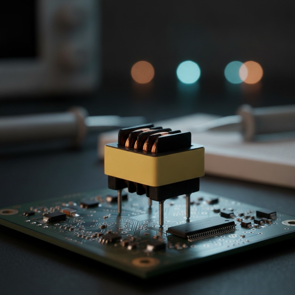
Core Construction and Mechanical Architecture
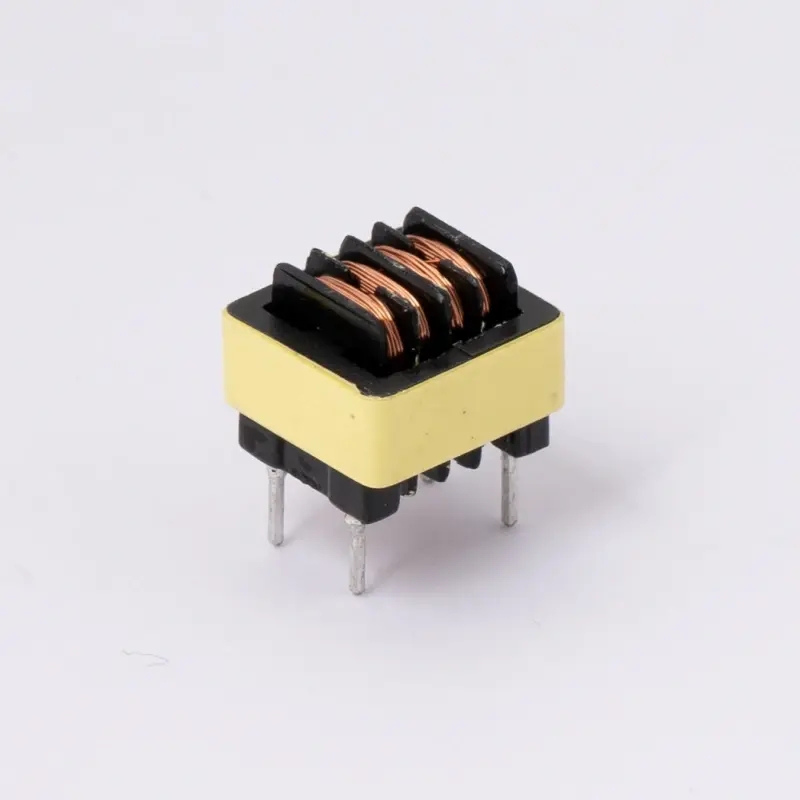
Structurally, the unit relies on an EE-type split ferrite core measuring roughly 8.3 mm along the primary core frame dimension, with an assembled height typically around 10 mm to 12 mm depending on the terminal base structure. Operating as a vertical through-hole common mode choke, the component positions its windings upright relative to the circuit board. This vertical posture occupies substantially less surface area than horizontal toroid or flat-laying bobbin arrangements, making it well-suited for high-density packing on dual-layer or multi-layer boards.
The core halves are secured around an insulating thermoplastic bobbin. Visible construction includes a yellow polyester adhesive tape wrap that provides mechanical containment for the split-core interface and winding layers. Terminal pins project downward from the bobbin base, finished with a solderable tin-plated layer suitable for conventional wave soldering or manual assembly processes. Depending on terminal base tooling, pin counts generally range between four and six leads, accommodating balanced twin-winding topologies.
Functional Role as an EE8.3 EMI Filter Inductor
In standard filter networks, the EE8.3 line filter inductor presents a high impedance to common-mode noise while allowing differential operational current to flow largely unhindered. When mains current or balanced DC power flows through the opposing phase windings in equal and opposite directions, the magnetic flux inside the closed ferrite loop cancels out, preventing saturation under normal operating current. Conversely, unwanted common-mode noise travelling in the same direction across both conductors creates an additive magnetic flux within the core, generating substantial reactive impedance that dissipates or reflects the interference.
Because switching power supplies regularly generate broadband noise across the standard regulatory conducted emission testing band (150 kHz to 30 MHz), this EE8.3 EMI filter inductor acts as a core frontline suppression element. Specific attenuation profiles and impedance curves will inevitably depend on the winding scheme, wire diameter, and permeability of the selected ferrite grade.
Material Specifications and Physical Profile
Reliable attenuation hinges on material integrity across the component stack:
Ferrite Core Geometry
The magnetic path is formed by an EE8.3 ferrite choke core with a dark, passivated surface finish to resist oxidation and suppress micro-arcing between adjacent conductive elements. The split-core architecture allows precise placement over pre-wound bobbins.
Winding Materials
Winding coils use enameled copper magnet wire, applied in uniform, machine-tensioned layers. Insulation on the wire provides dielectric isolation between turns, while the bobbin walls provide primary creepage and clearance between opposing line windings.
Structural Bobbin and Terminations
The molded base is made from high-temperature rigid thermoplastic, providing pin stability during insertion and wave soldering. Pin pitches and spatial offsets are set within the molding tool, establishing mechanical stability once seated against the PCB surface.
Manufacturing Sequence and Quality Verification
The production flow for this EE8.3 common mode inductor follows established industrial magnetic fabrication steps:
1. Precision winding: Magnet wire is coiled onto multi-chamber or partitioned thermoplastic bobbins via multi-spindle automatic winding equipment.
2. Core assembly: EE core halves are inserted into the bobbin cavity and mated tightly. Mating faces must remain clean of particulate matter to prevent unintended air gaps that degrade permeability.
3. Retention banding: Outer layers of electrical-grade polyester tape are tension-wrapped around the core exterior to secure the core halves against thermal shock and mechanical vibration.
4. Termination: Copper lead-outs are stripped, routed into the terminal pins, and dipped in molten solder alloy for tinning.
5. Production testing: Coils undergo testing for inductance, DC resistance balance between windings, and dielectric withstand (hi-pot) between independent circuits to ensure insulation safety before packaging.
Application Scenarios
Engineers specify this power supply common mode inductor across space-limited low-to-medium power conversion platforms:
- AC-DC power adapters and high-efficiency wall chargers.
- Compact LED drivers and solid-state lighting ballasts where low physical profile is essential.
- Auxiliary power supply rails and standby circuits in white goods, industrial instrumentation, and smart metering devices.
- DC-DC filtering networks within telecommunications hardware and automation control boards.
Specification Guidance for Custom Common Mode Choke Projects
While the EE8.3 mechanical profile is an industry standard, electrical performance must align with specific circuit operating points. When configuring a custom common mode choke for a design project, engineering teams should evaluate several baseline variables:
- Nominal and peak operating current to select suitable wire gauge without excessive temperature rise.
- Target common-mode impedance and inductance requirements corresponding to problematic conducted emission peaks.
- Dielectric isolation requirements between input-to-output or phase-to-neutral windings to satisfy end-product safety standards.
- Pin spacing and lead diameter tolerances to ensure drop-in compatibility with standard automated pick-and-place or insertion lines.
Contact for Technical Specifications and Samples
For detailed dimensional drawings, pin assignments, and customized winding options for the EE8.3 common mode choke, submit your target schematic parameters, current limits, and testing standards to our engineering department for prototyping support.