
Overview of the SQ1824 Common Mode Choke
Conducted electromagnetic interference presents a persistent challenge in switch-mode power supplies and AC/DC conversion stages, frequently pushing designs beyond statutory emissions thresholds. The SQ1824 common mode choke addresses this problem by introducing high impedance against asymmetrical noise currents while presenting minimal impedance to normal differential load currents. Built in a compact vertical form factor, this passive suppression component targets power design engineers who need significant attenuation within a constrained board footprint.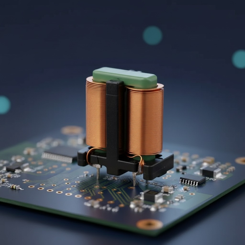
Functioning as both an EMI filter inductor and an isolation element, the component incorporates two separate, phase-opposed copper windings linked by a magnetic core. When line-borne common-mode currents pass through the windings, their magnetic fluxes reinforce one another inside the core material, attenuating the unwanted noise before it couples into surrounding circuitry or reflects back onto the main power grid.
Structural Geometry and Mechanical Configuration
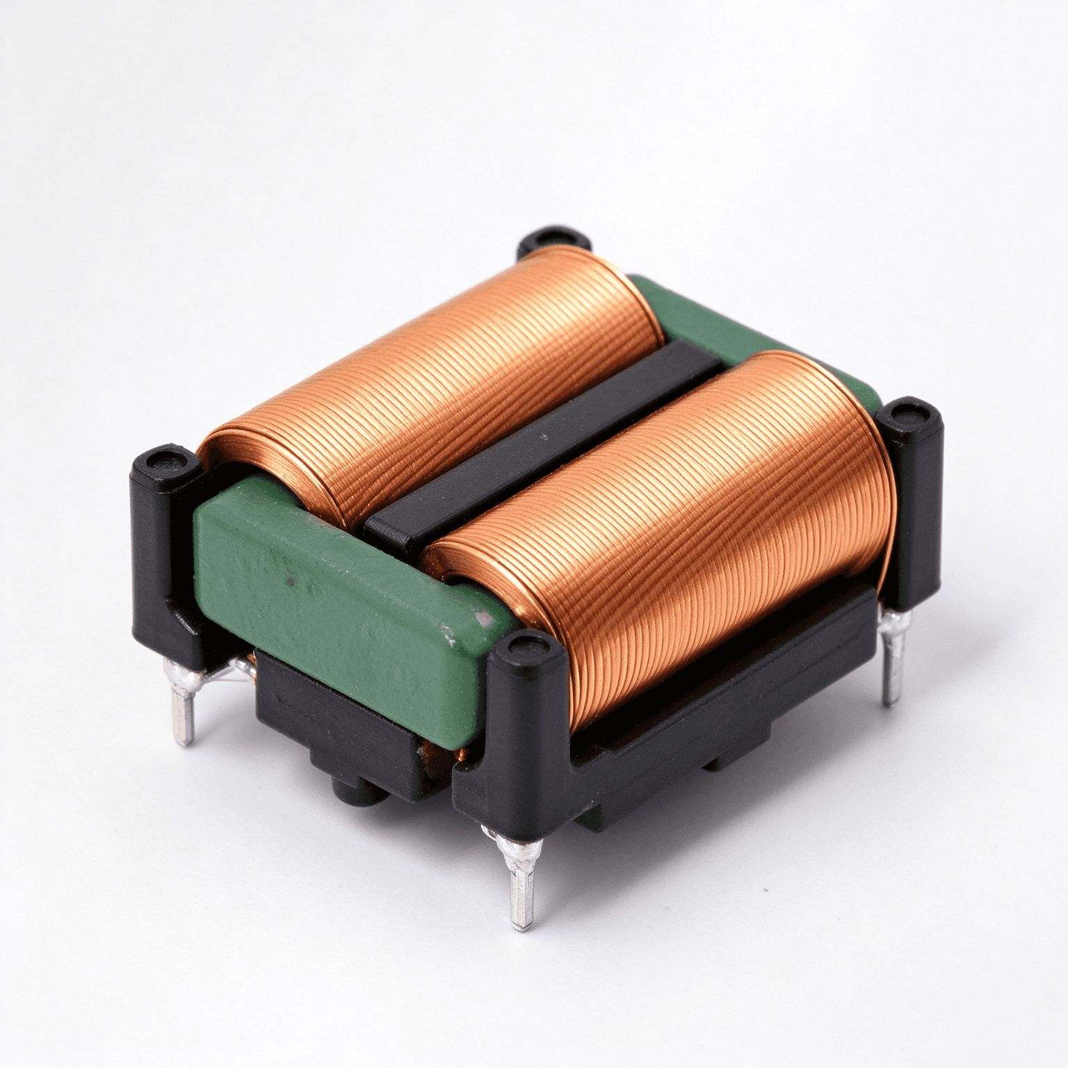
Unlike traditional horizontal toroidal chokes that consume considerable PCB surface area, this component operates as a vertical common mode choke. The winding axes run perpendicular to the circuit board, concentrating the physical bulk upward to conserve valuable layout margins between input stages, bulk capacitors, and power switches.
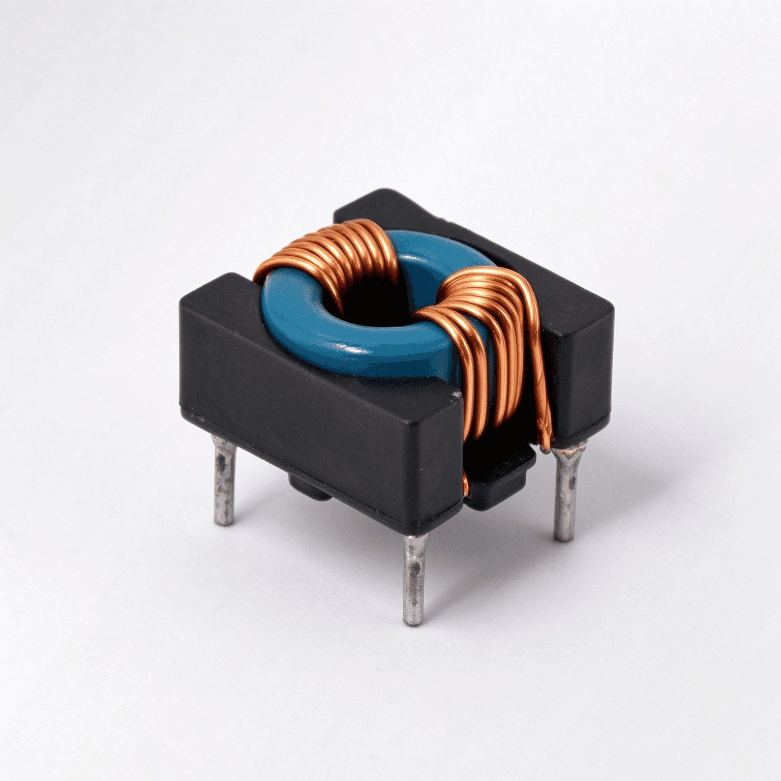
The component is built around a molded black engineering plastic bobbin, typically manufactured from nylon or PET-grade thermoplastic. This bobbin provides distinct dual winding chambers divided by a solid vertical insulating barrier, maintaining creepage and clearance distances between the complementary line coils. The mounting base integrates downward-facing terminal pins, establishing it as a rugged through-hole common mode inductor well-suited for automated assembly lines and standard wave-soldering processes. While terminal pin count and specific pitch patterns require verification against factory datasheets, the visible architecture reveals multiple robust leads anchored into the base structure.
Materials and Core Architecture
Visible inspection reveals a bridge-style magnetic structure capped with an epoxy-finished green segment across the top of the coil sections. This protective green coating strongly indicates a MnZn ferrite choke, a material class commonly specified for line-frequency noise suppression due to high initial permeability in the low-to-medium megahertz spectrum. Designers should note, however, that exact permeability coefficients, core losses, and temperature-dependent saturation profiles vary across ferrite grades and must be referenced from individual batch specifications.
The coils utilize closely layered copper conductors, designated as a flat wire common mode choke. Utilizing rectangular or flat magnet wire allows higher conductor cross-sections relative to standard round wire, which inherently reduces DC winding resistance and optimizes slot fill factors. This tight mechanical packing minimizes parasitic capacitance between winding layers, thereby extending high-frequency suppression characteristics.
Manufacturing and Assembly Sequence
Producing the SQ1824 common mode inductor involves several automated coil-winding and assembly processes:
Precision Coil Formation
High-speed winding equipment layers the flat copper magnet wire onto the respective sections of the partitioned bobbin. Maintaining uniform tension prevents deformation of the rectangular conductor edges and preserves enamel insulation integrity across tightly radiused turns.
Core Placement and Structural Bonding
The ferrite core segments are inserted around and through the bobbin geometry. Specialized structural adhesives bond the core elements into a closed magnetic circuit, securing the assembly against mechanical vibration and acoustic humming induced by high ripple currents.
Lead Termination and Finishing
Winding ends are stripped of insulation, routed to the integrally molded base terminals, and soldered. Pins undergo mechanical squaring and hot-dip tinning to ensure uniform solderability during through-hole assembly.
Application Environments and Operational Roles
The SQ1824 common mode choke is predominantly implemented in line-input and intermediate conversion stages requiring compact electromagnetic compatibility management. Primary applications include:
Switch-Mode Power Supplies (SMPS) and industrial AC/DC converters, where it serves as a frontline power supply EMC choke preventing high-frequency switching noise from propagating back to the utility grid.
LED lighting drivers and commercial luminaire ballasts, where vertical packaging satisfies strict height-versus-width enclosure envelopes.
Industrial motor drives, automation control boards, and consumer appliance power modules that mandate robust mechanical anchoring against sustained mechanical shock and thermal cycling.
Quality Control and Validation Protocols
Manufacturing consistency across production batches requires dedicated verification steps:
Electrical Balance Verification
Common-mode attenuation relies heavily on phase and inductance balance between the paired windings. Quality control involves measuring nominal inductance (mH) on precision LCR meters, confirming that mutual inductance matches and leakage inductance remains within design tolerances.
Hi-Pot and Insulation Integrity
Dielectric withstand tests verify the barrier integrity provided by the central bobbin divider, ensuring reliable isolation between input phases or between line and neutral paths under transient surge voltages.
Mechanical Inspection
Optical verification systems inspect terminal pin coplanarity, solder fillet coverage on pin joints, and the absence of micro-fractures in the brittle MnZn ferrite body.
Buyer Decision Factors and Selection Guidance
When integrating the SQ1824 common mode choke into a bill of materials, engineering and procurement teams should evaluate several baseline variables:
Package Footprint vs. Envelope Limits: The "1824" nomenclature typically denotes nominal base dimensions (approximately 18 mm by 24 mm), though exact clearance dimensions and total vertical height must be confirmed via manufacturer drawings prior to Gerber release.
Thermal and Current Derating: While flat-wire architecture aids thermal dissipation and current handling, nominal rated current, peak ambient operating thresholds, and temperature-rise limits must align with end-product enclosure thermals.
Termination and Board Layout: Confirm pinout designations—including whether the internal winding arrangement is straight-through or cross-pinned—to avoid accidental phase inversion during PCB routing.
Technical Inquiries and Component Sourcing
For complete electrical data including insertion loss curves, DC resistance figures, rated current boundaries, and custom turn configurations based on the standard SQ1824 bobbin platform, contact engineering support to request certified product documentation and production samples.